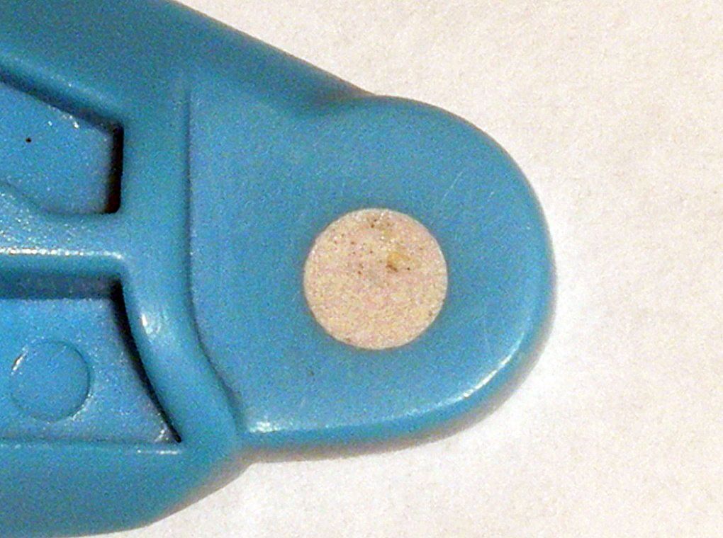
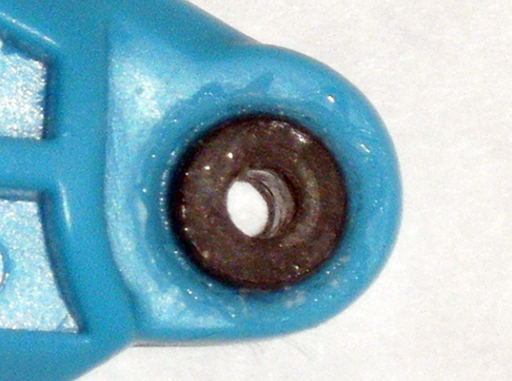
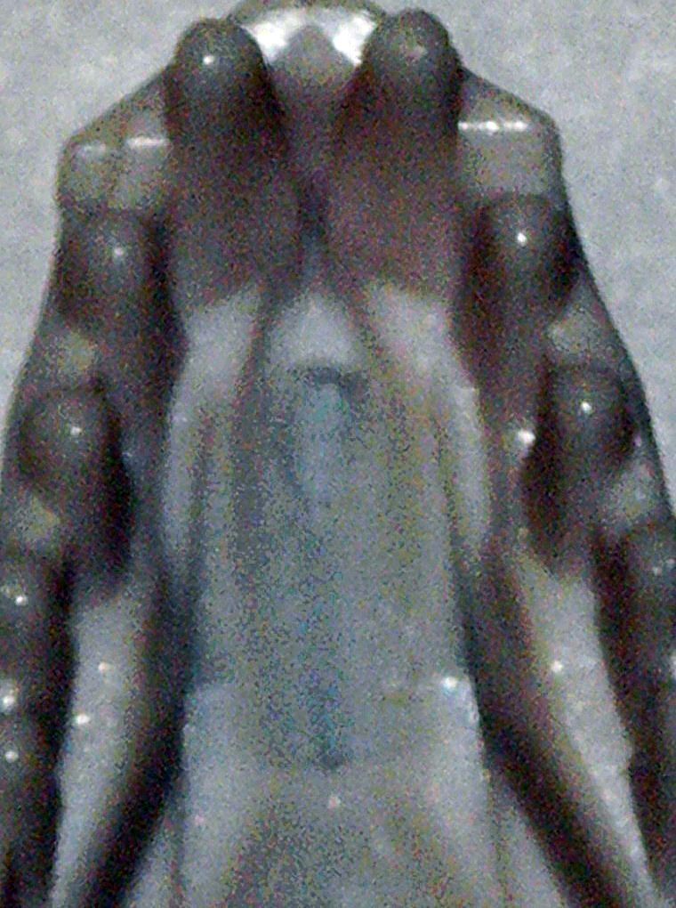
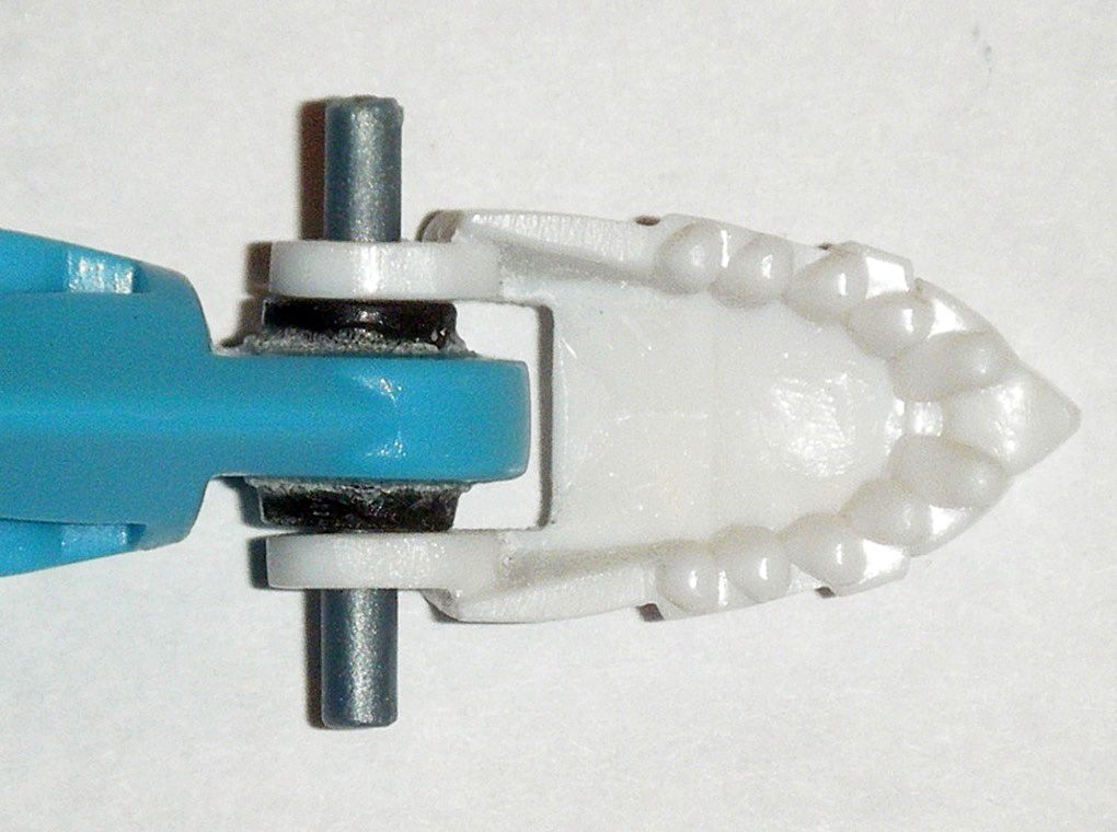
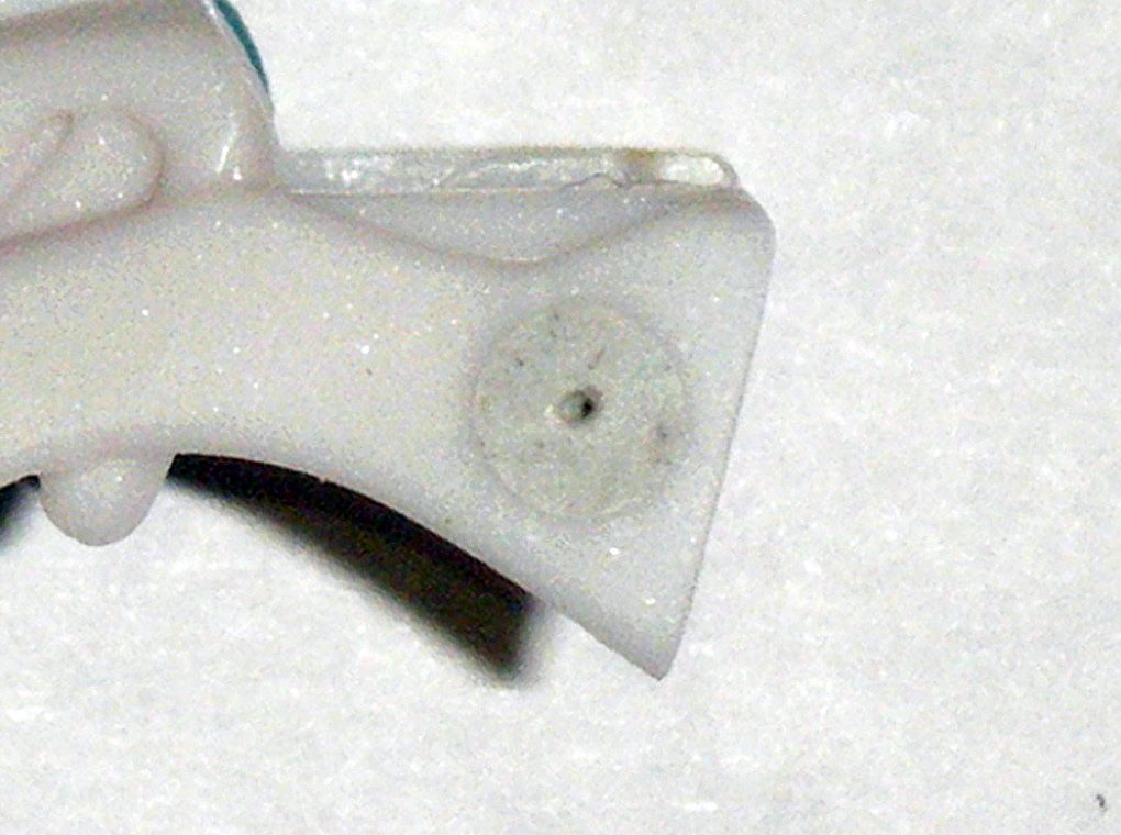
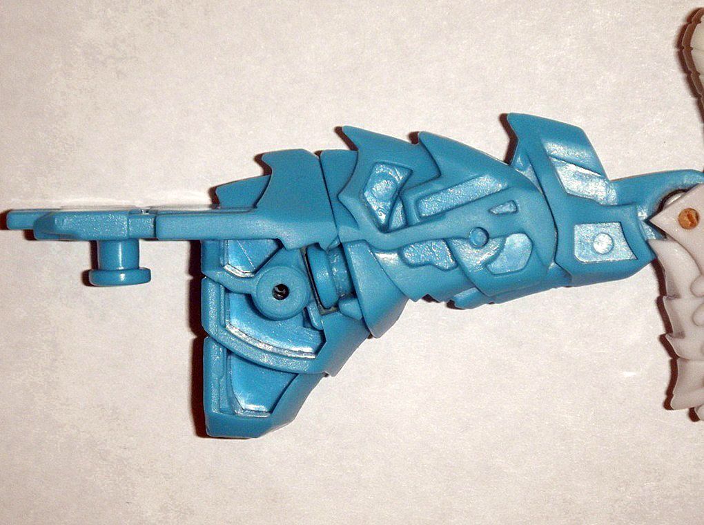
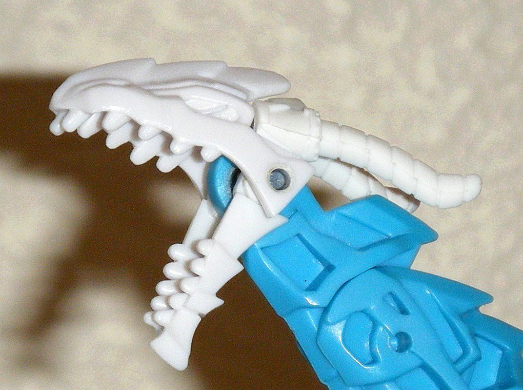
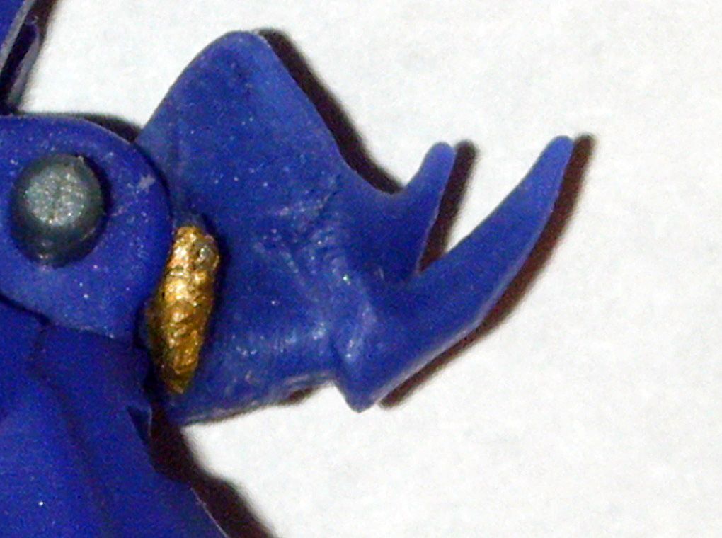
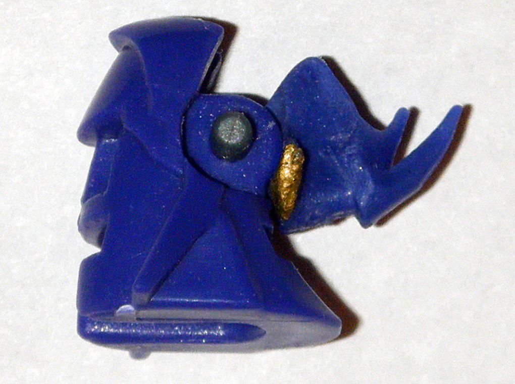
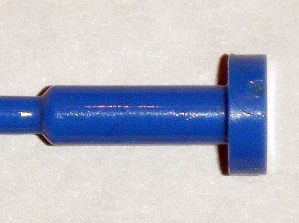
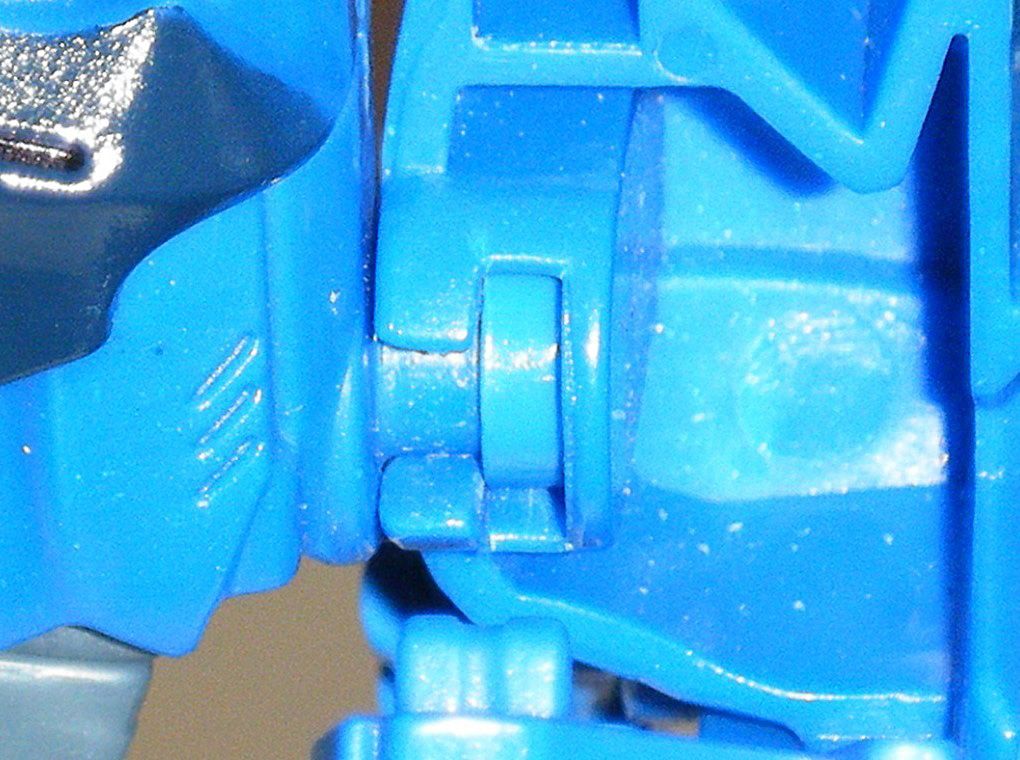
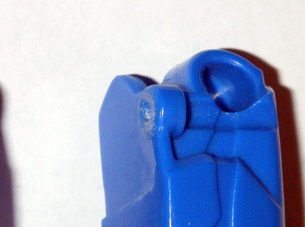
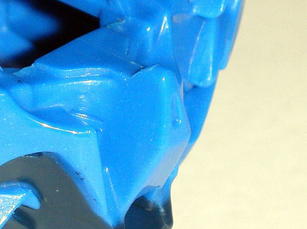
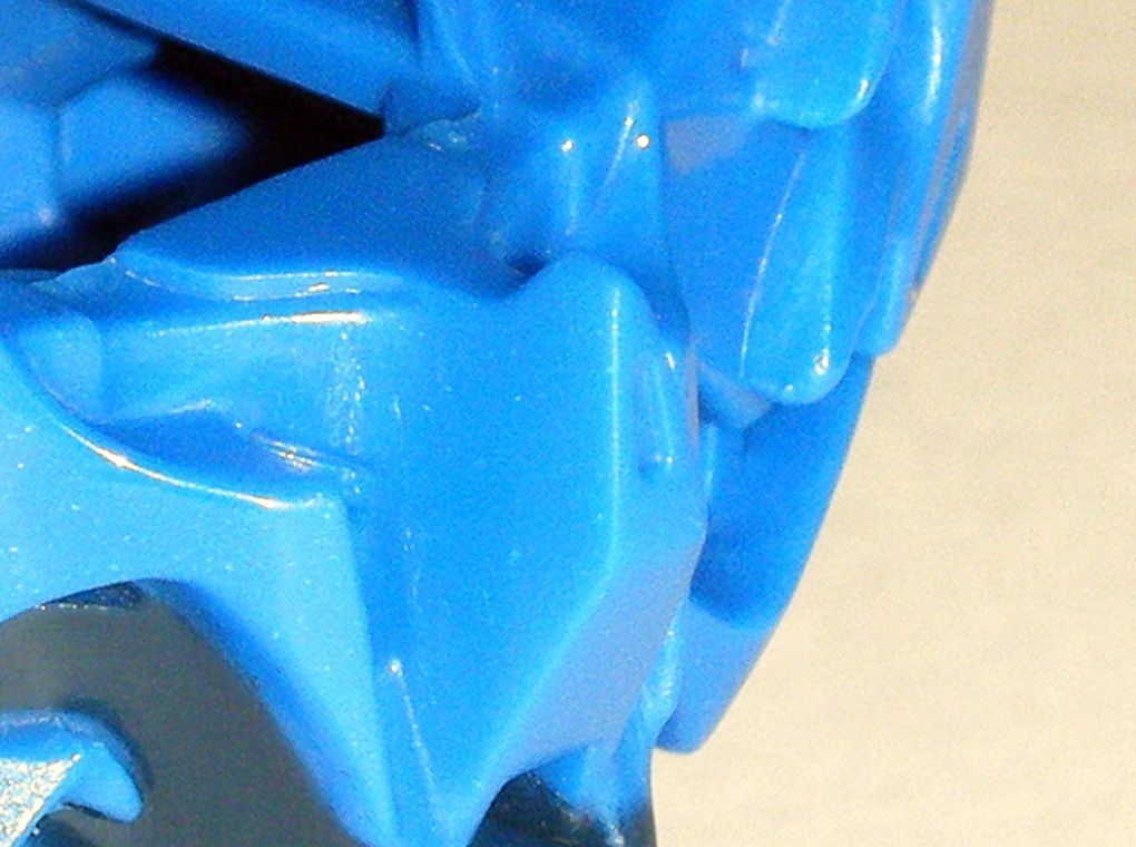
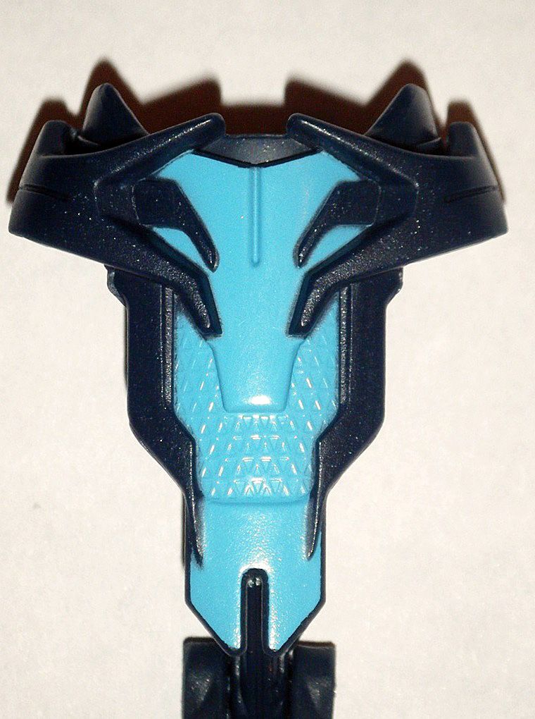
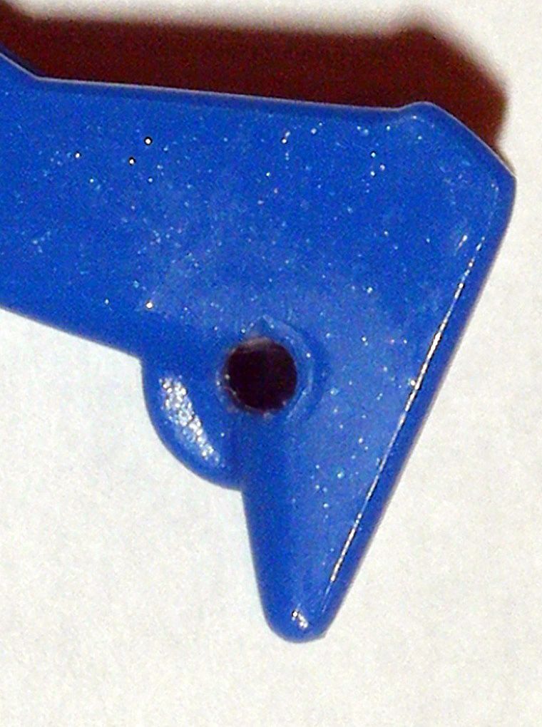
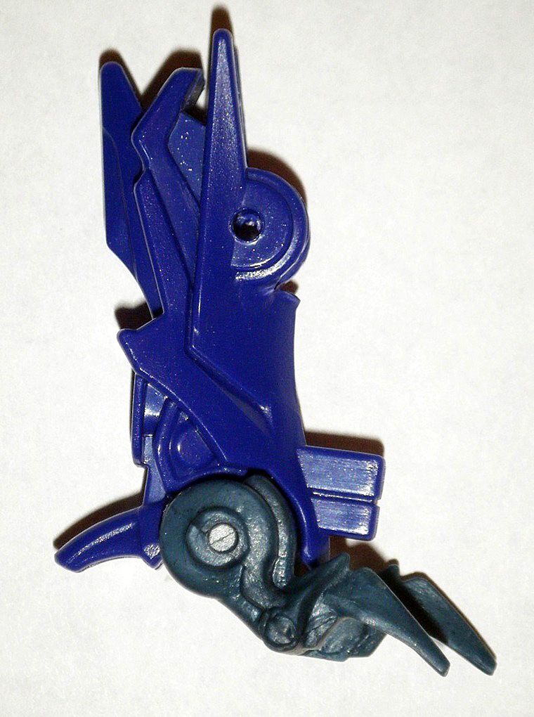
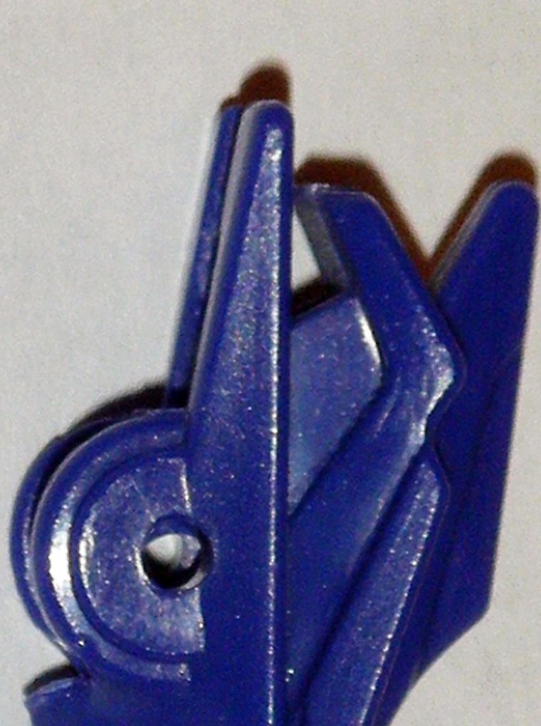
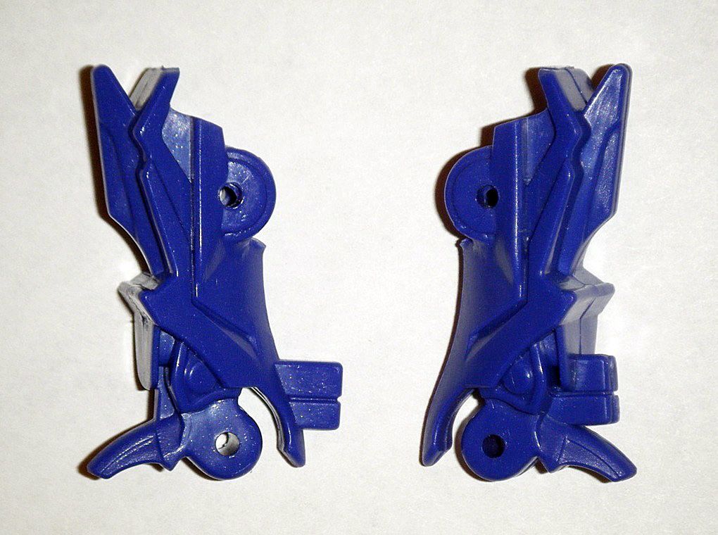
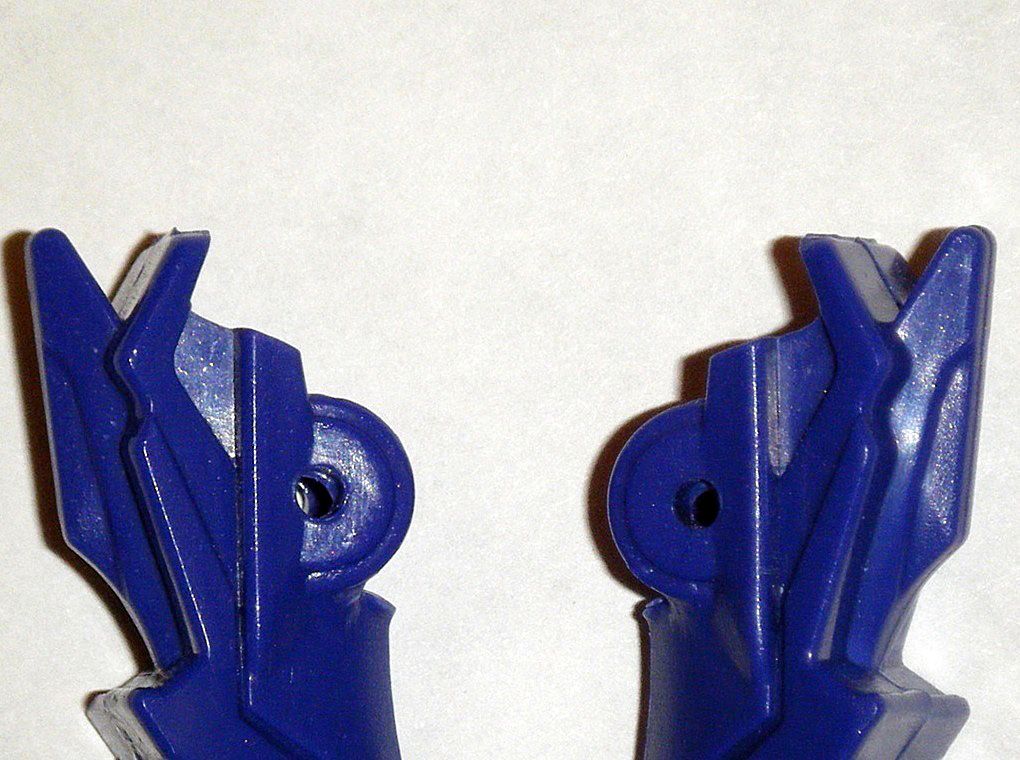
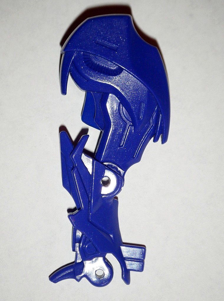
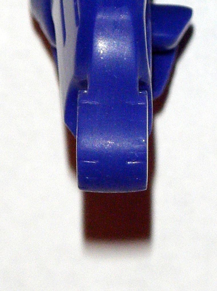
C) TUTORIAL:A) ALTERNATE MODE HEAD & NECK:01) Removed original alternate mode head by cutting of stopper ends of plastic rivet that held it on:
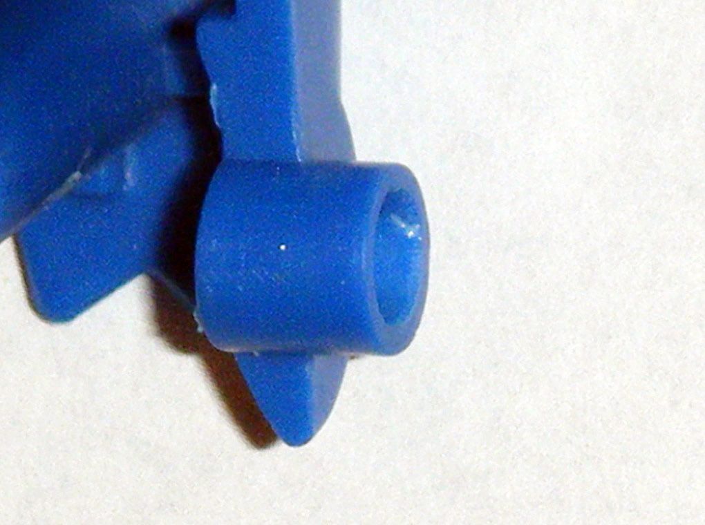
02) Cut off the “throat spike” at the head mount area, then sanded and polished it down:
03) Applied
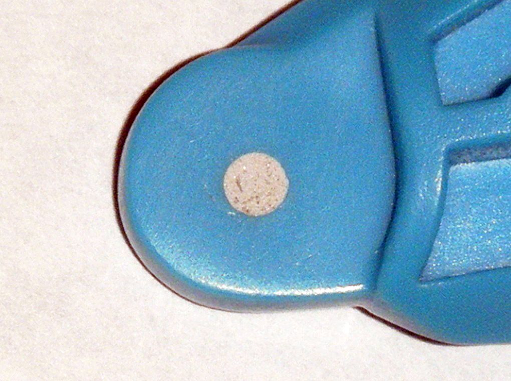
Epoxy Repair Putty over the rivet hole and let fully cure for a week after application:
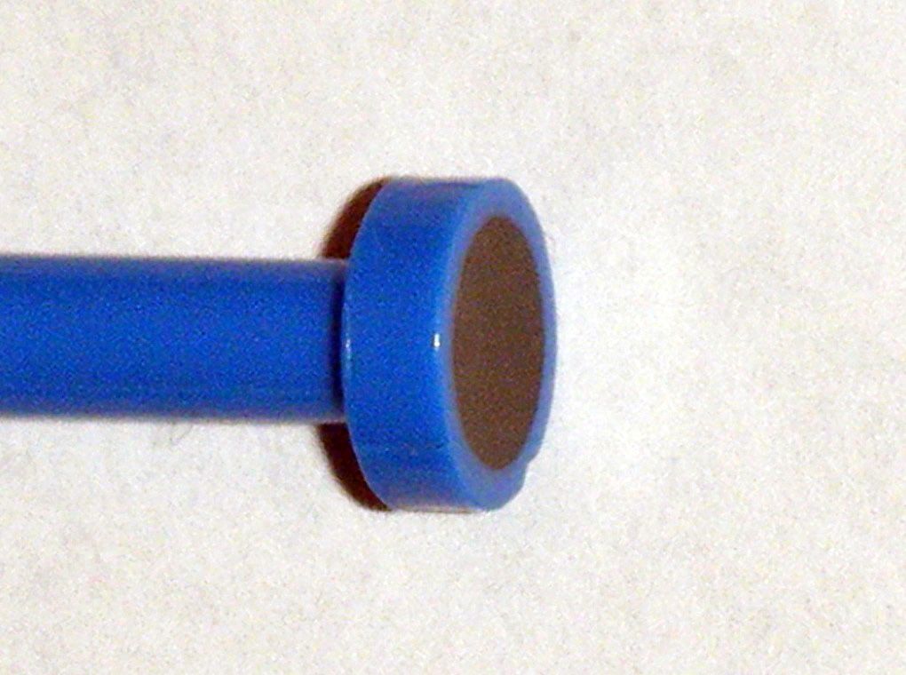
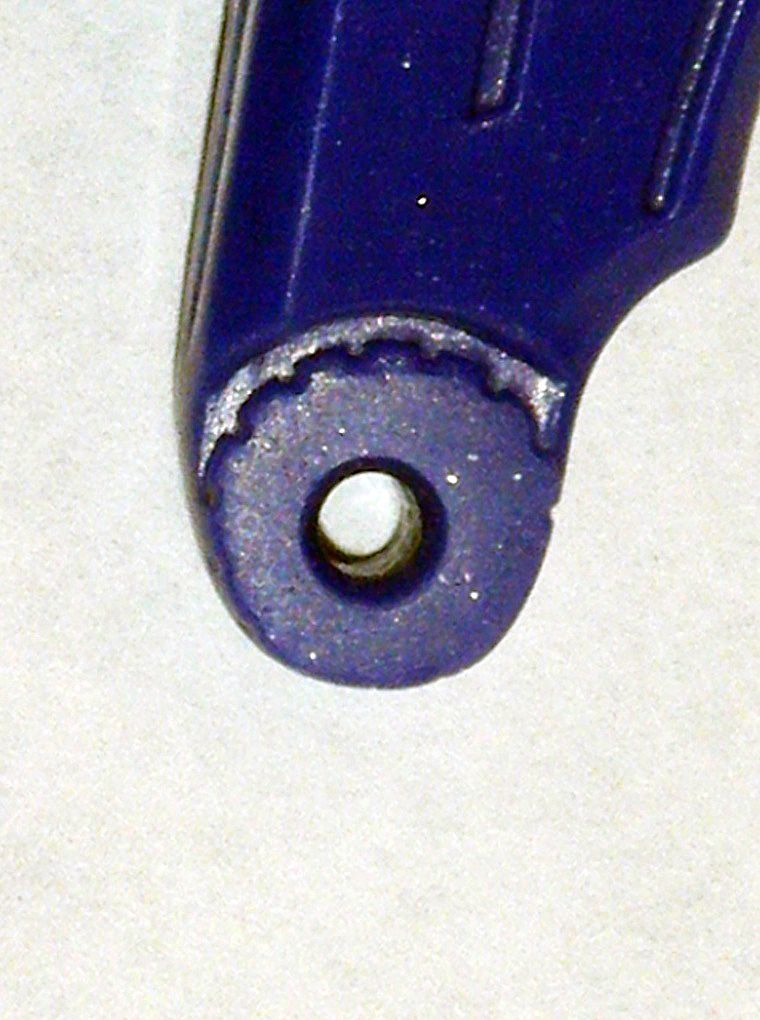
04) After said week, area was carefully sanded down flat and polished:
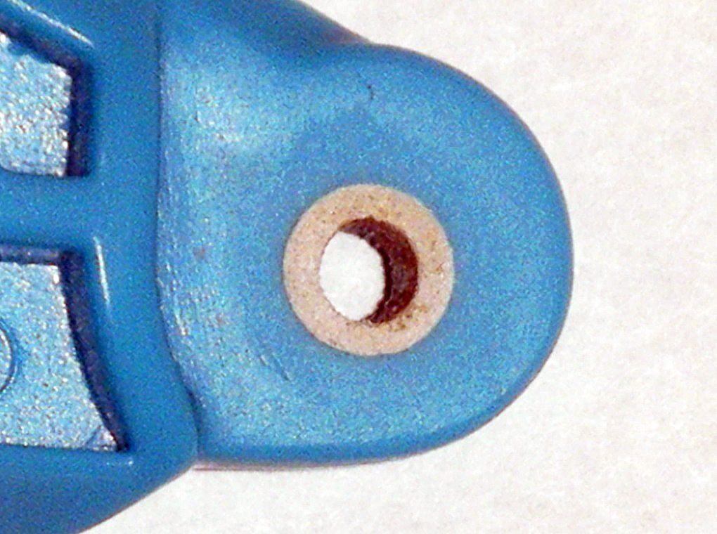
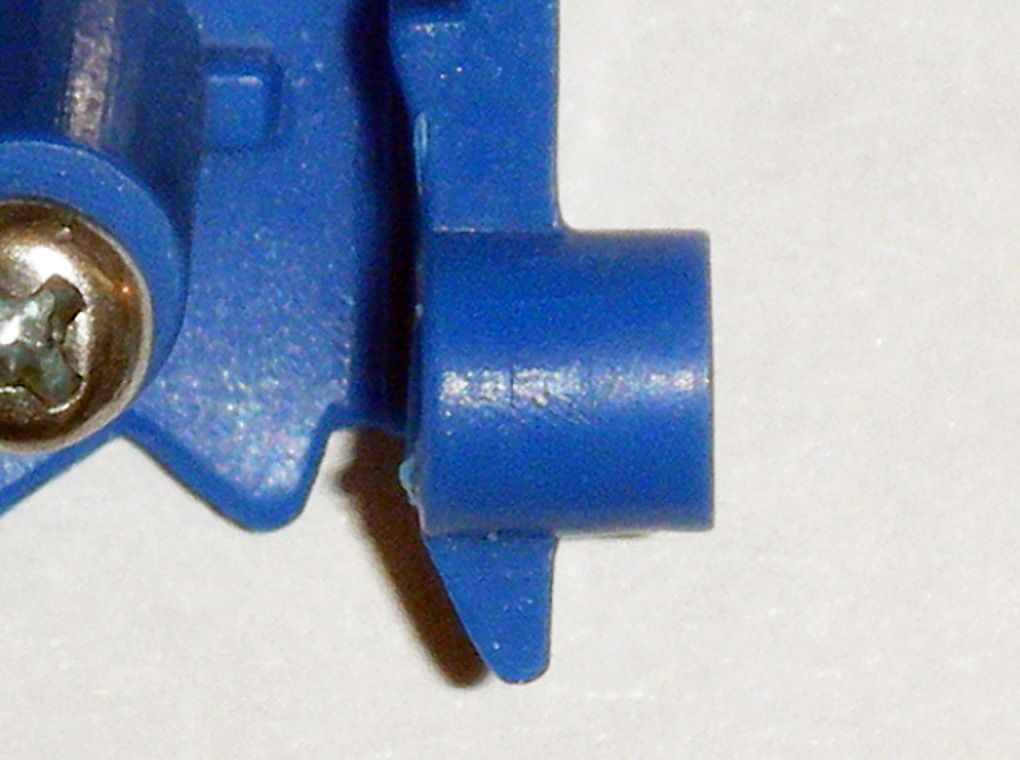
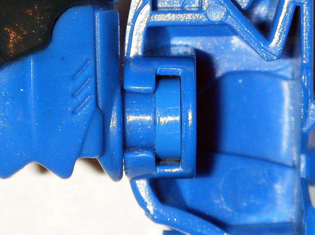
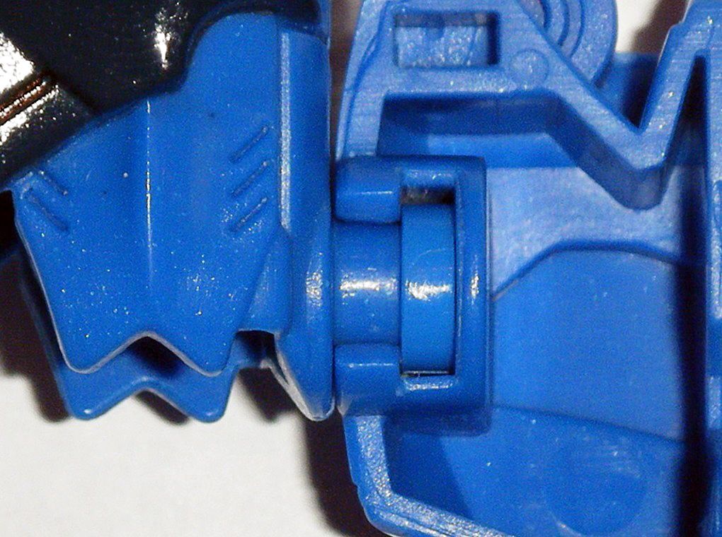
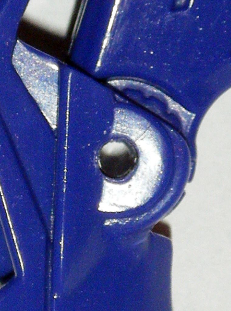
05) Carefully drilled hole through at low speed using, in order
Dremel 1/32”,
3/64”,
1/16” drill bits,
ACE 5/64” drill bit:
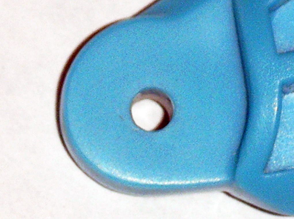
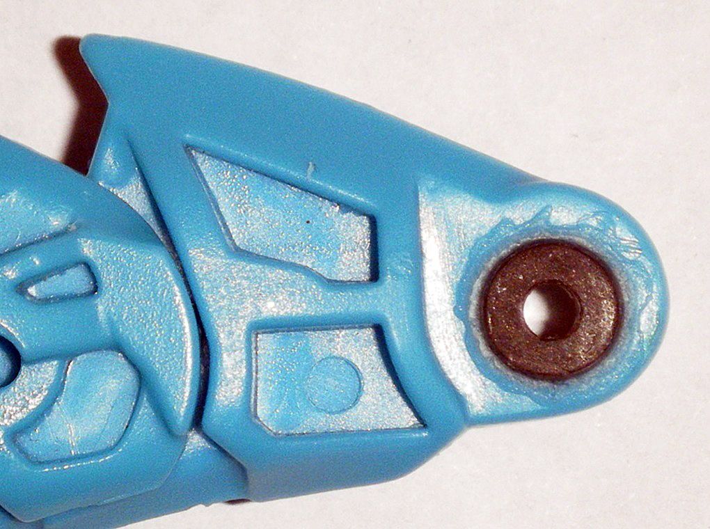
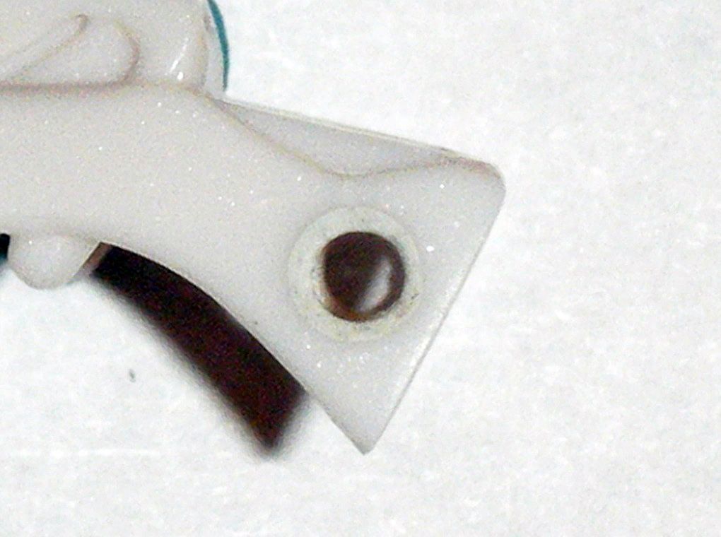
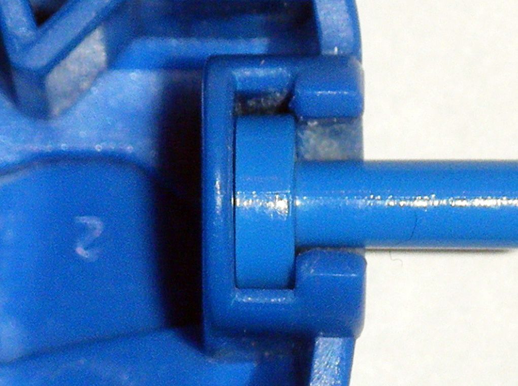
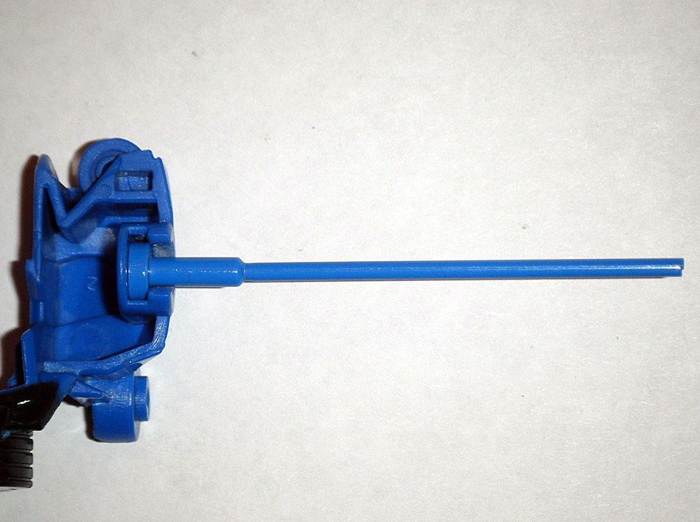
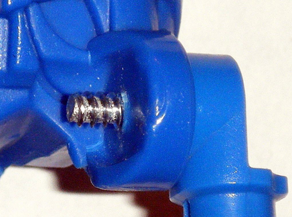
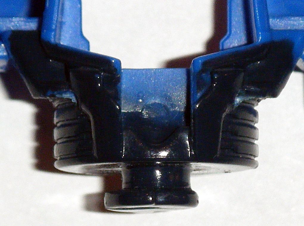
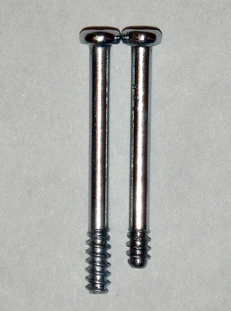
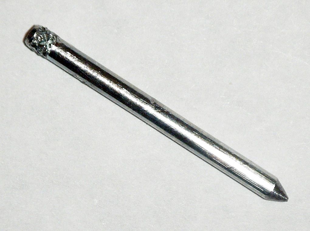
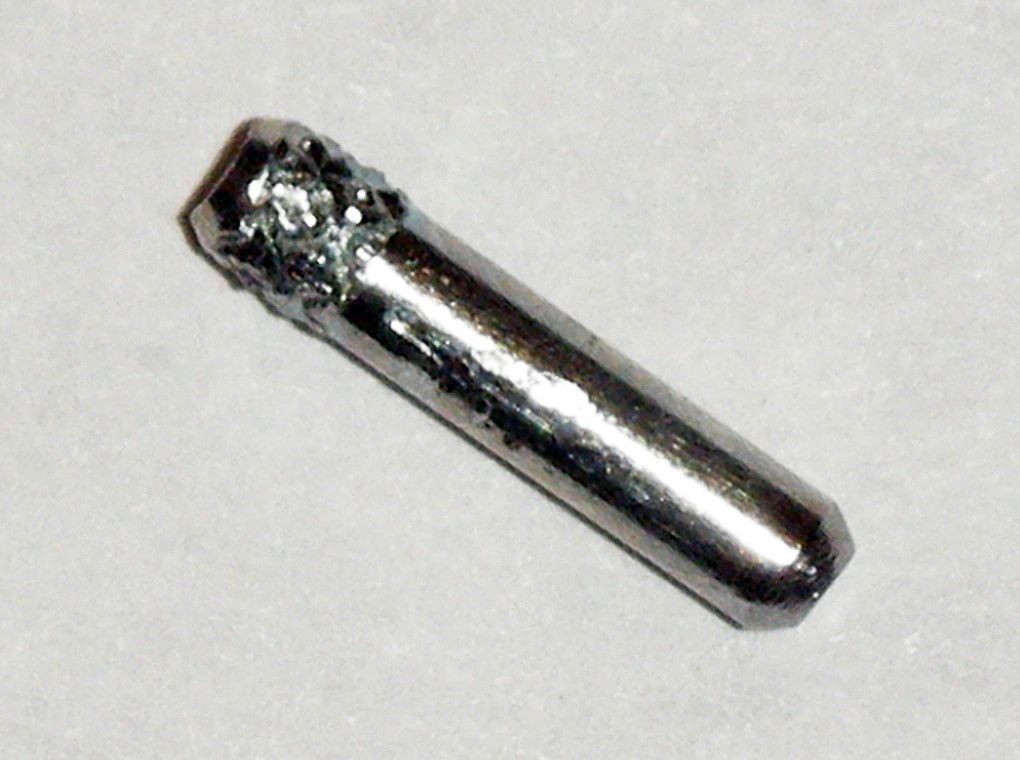
06) Threaded rivet through hole in order slide and glued 1 small black washer from inside cannon arm of
ROTF Voyager Megatron on each side:
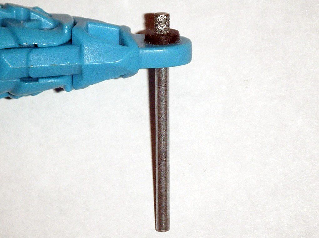
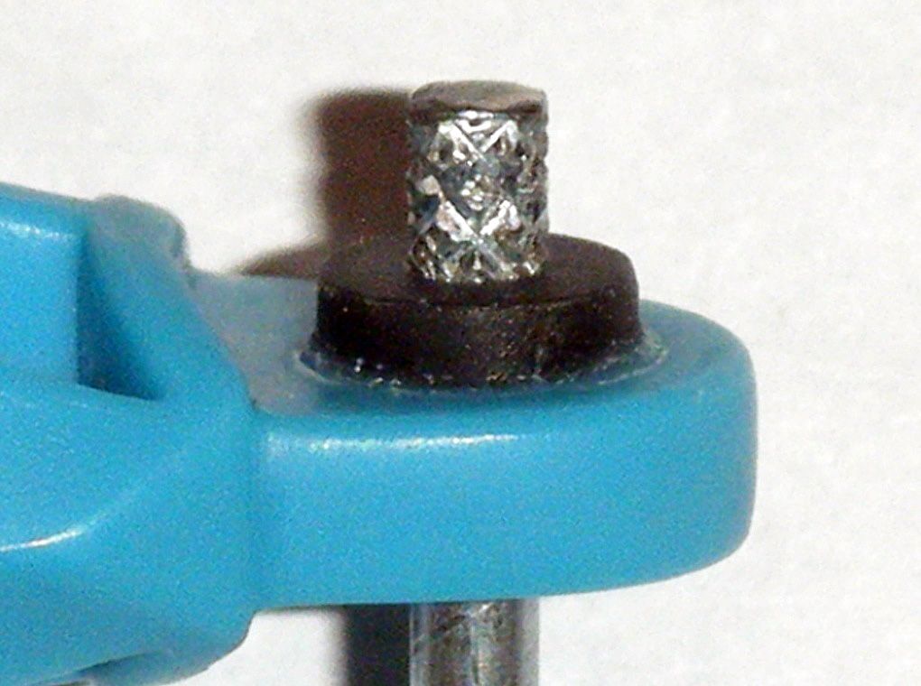
07) Used one
M2 2MM x 25MM Machine Screw with Nut to hold washers on and cure for a week:

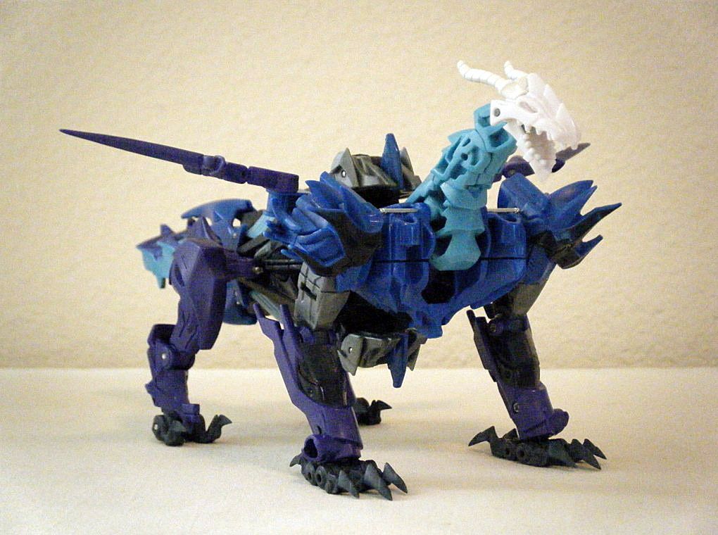
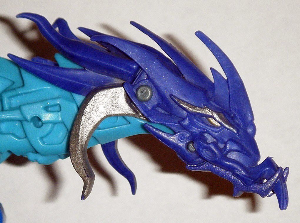
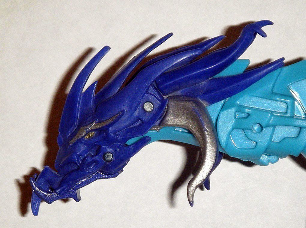
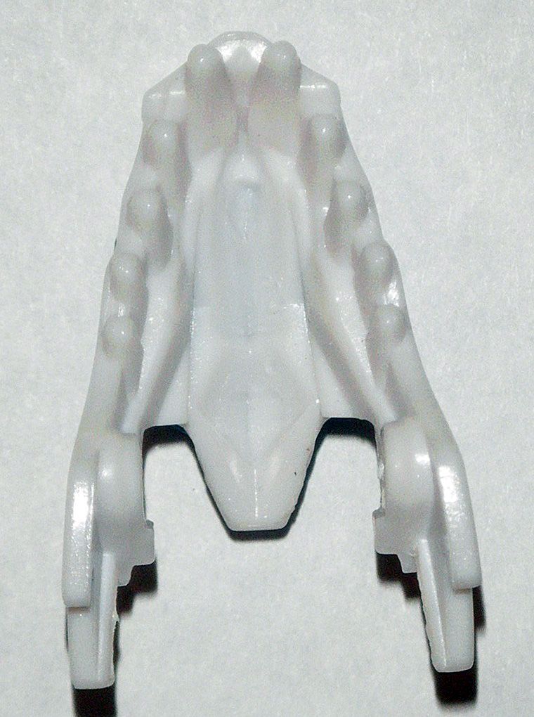
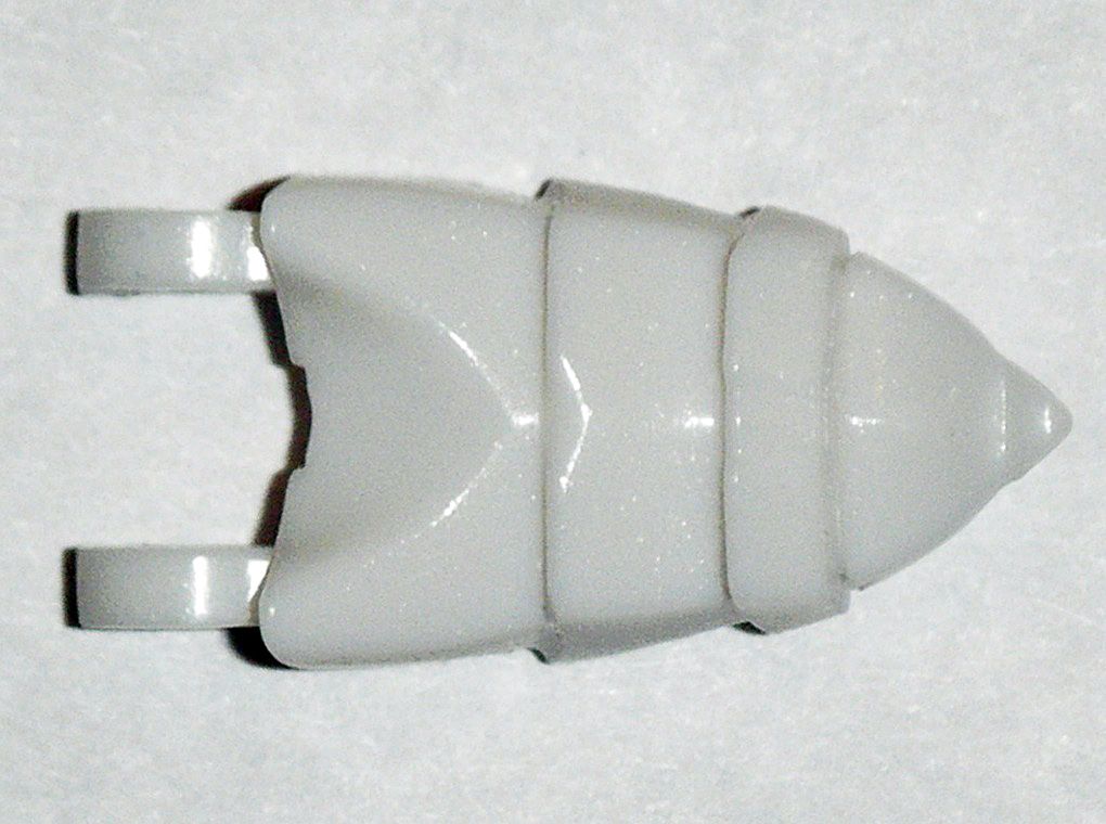
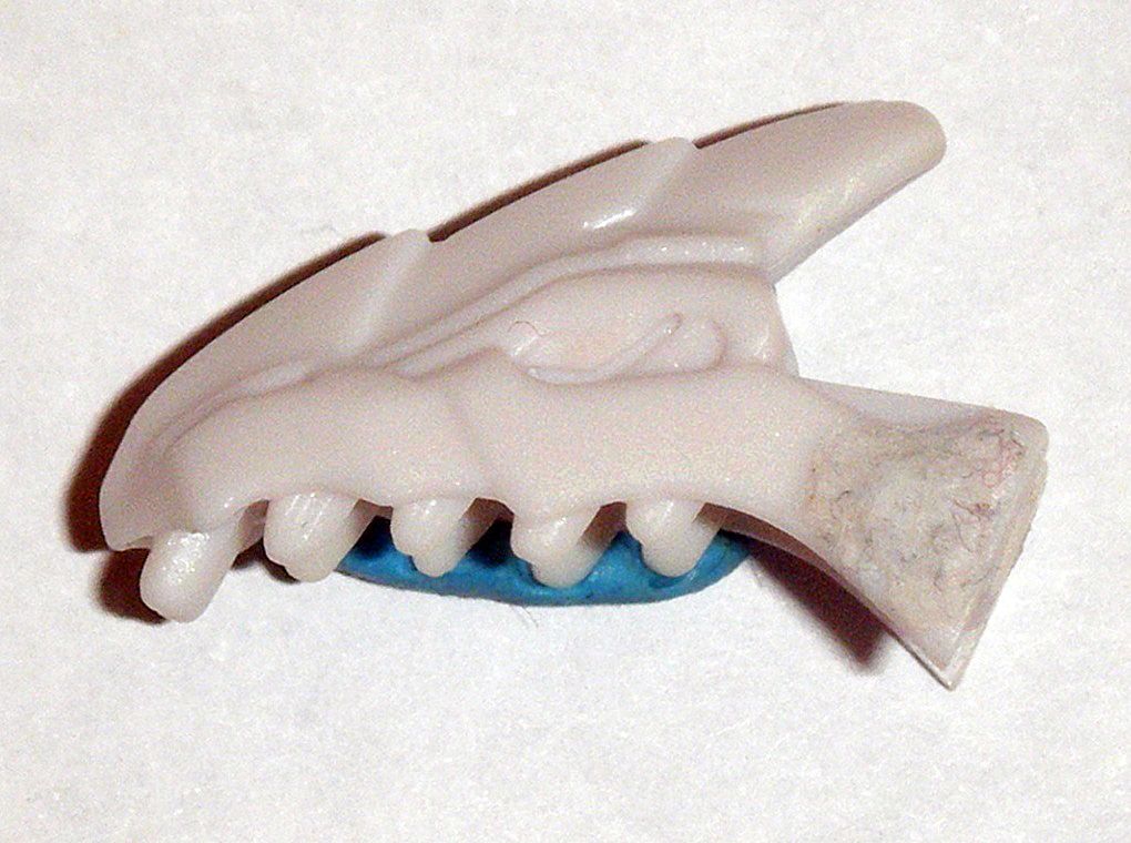
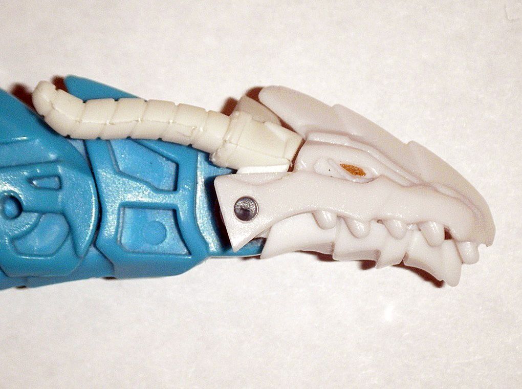
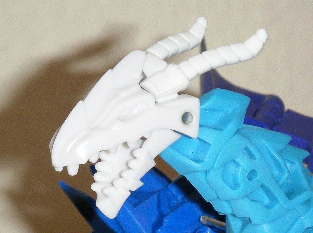
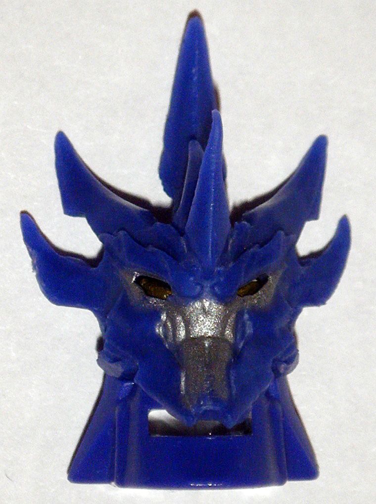
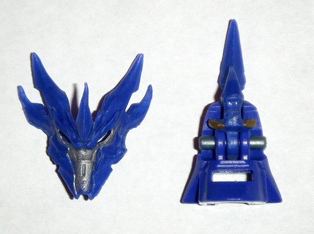
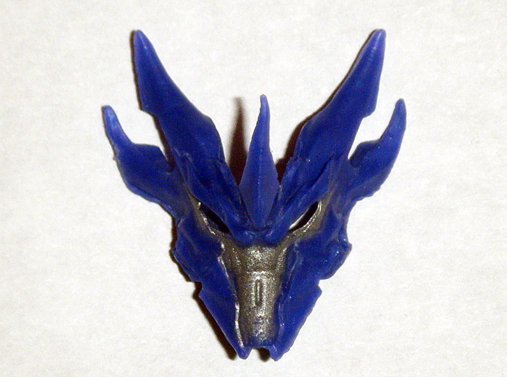
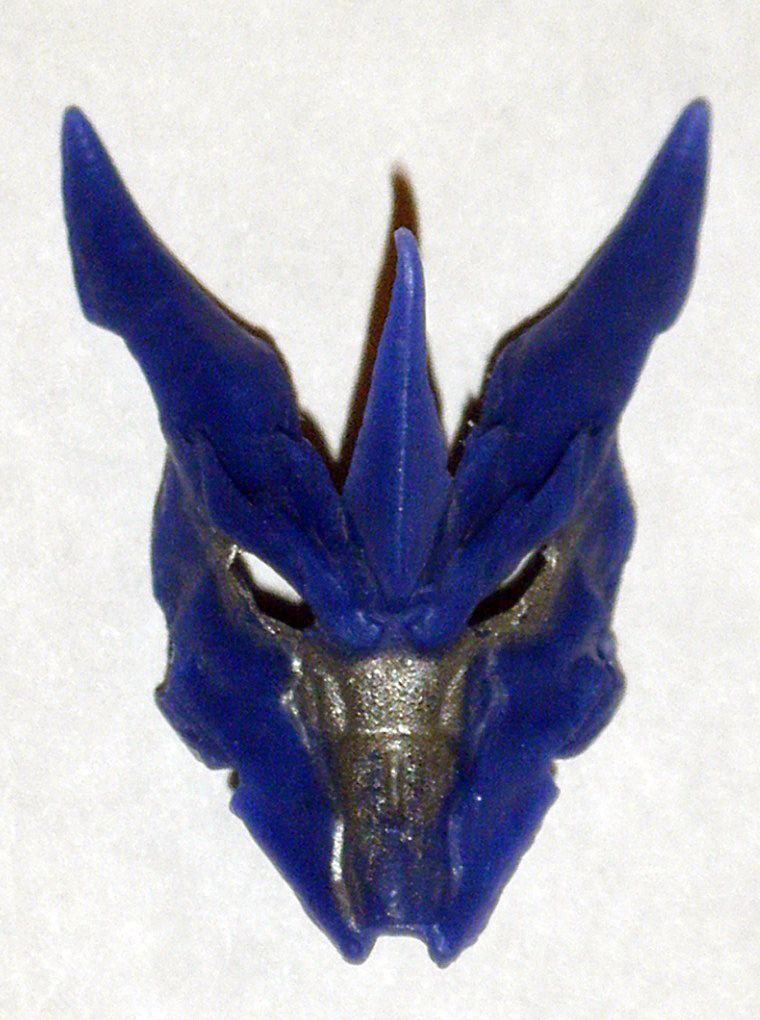
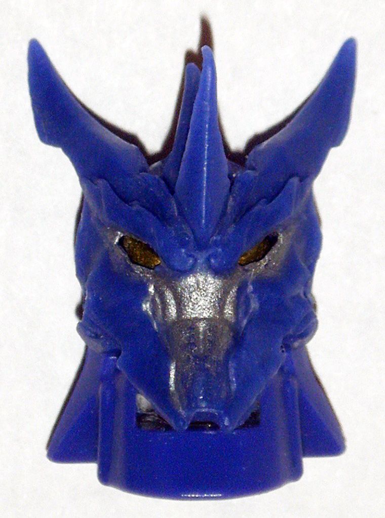
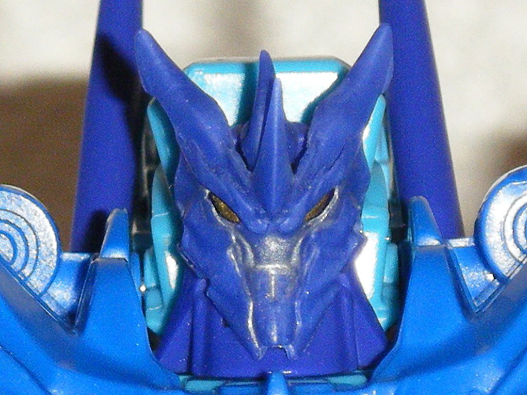
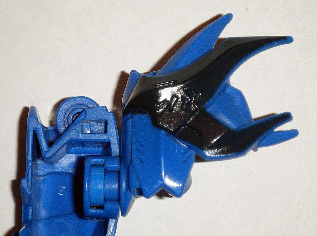
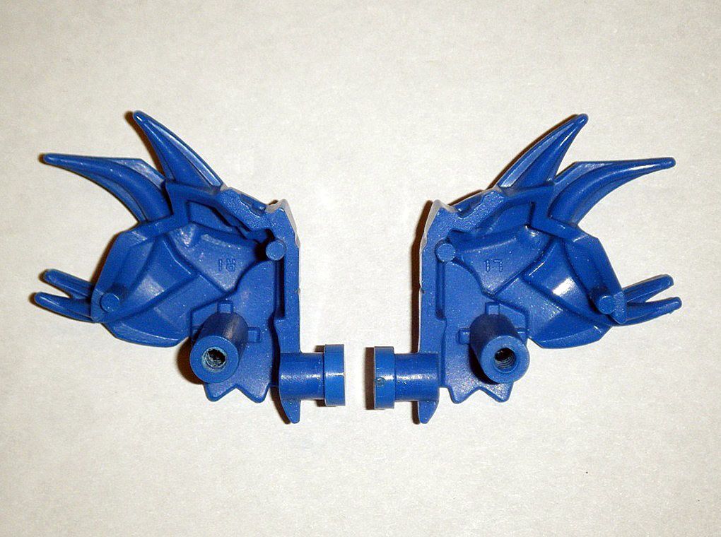
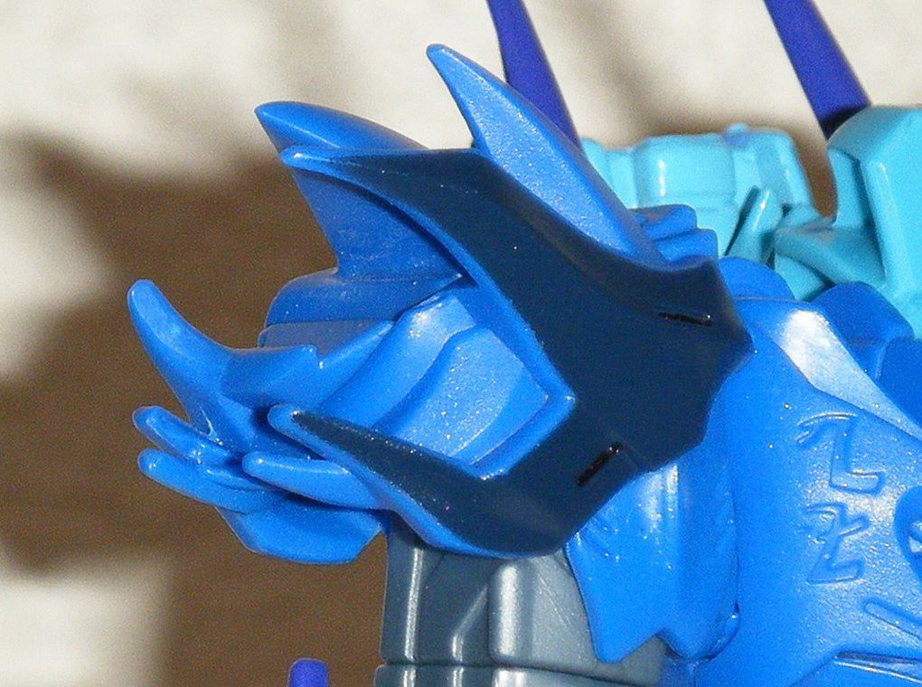
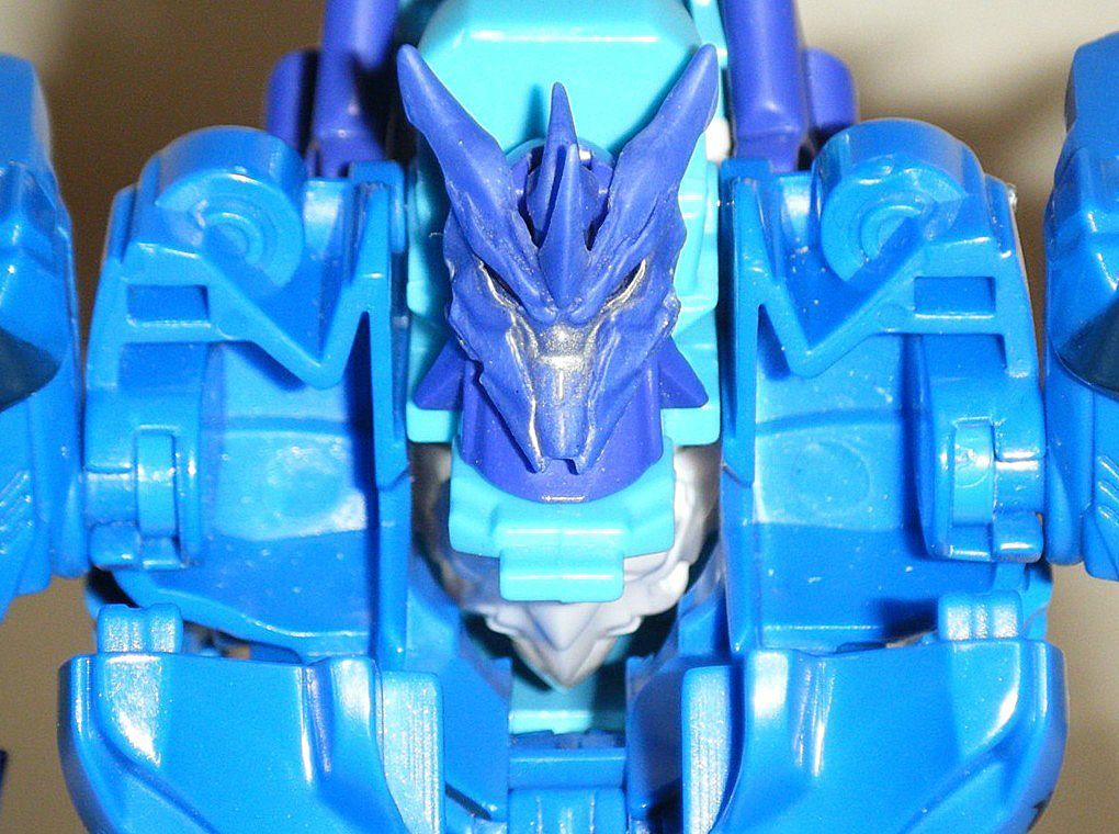
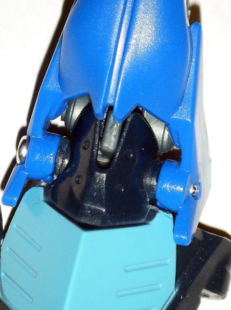
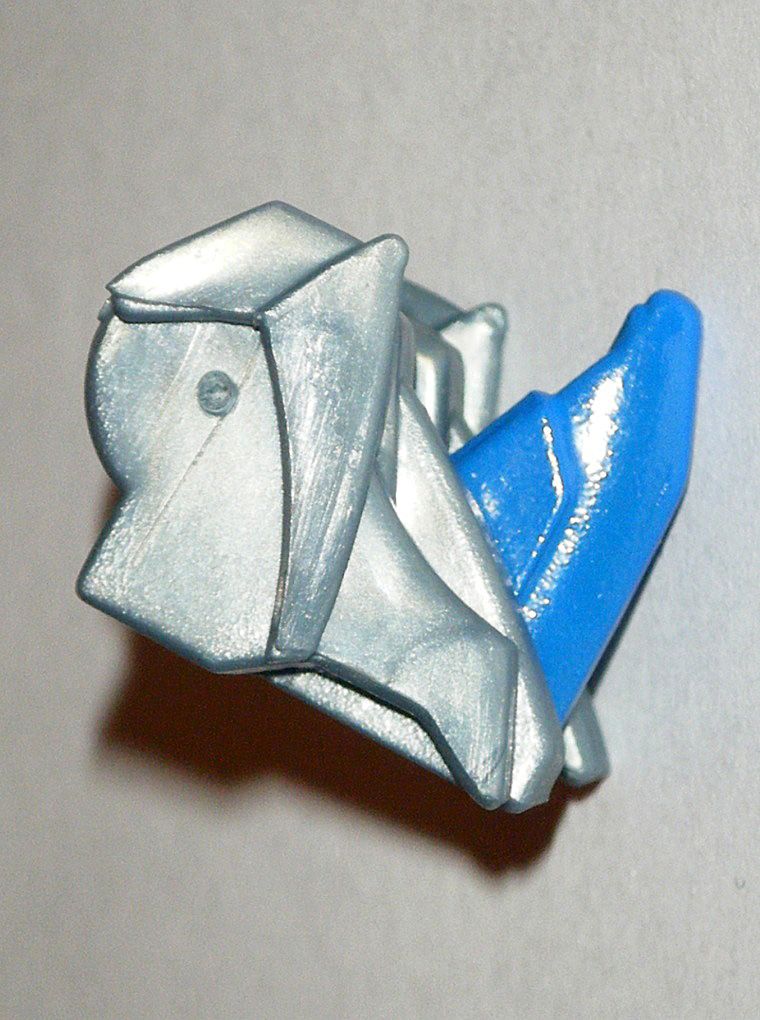
08) His new alternate mode head, the one from
Predacons Rising Deluxe Skylynx:
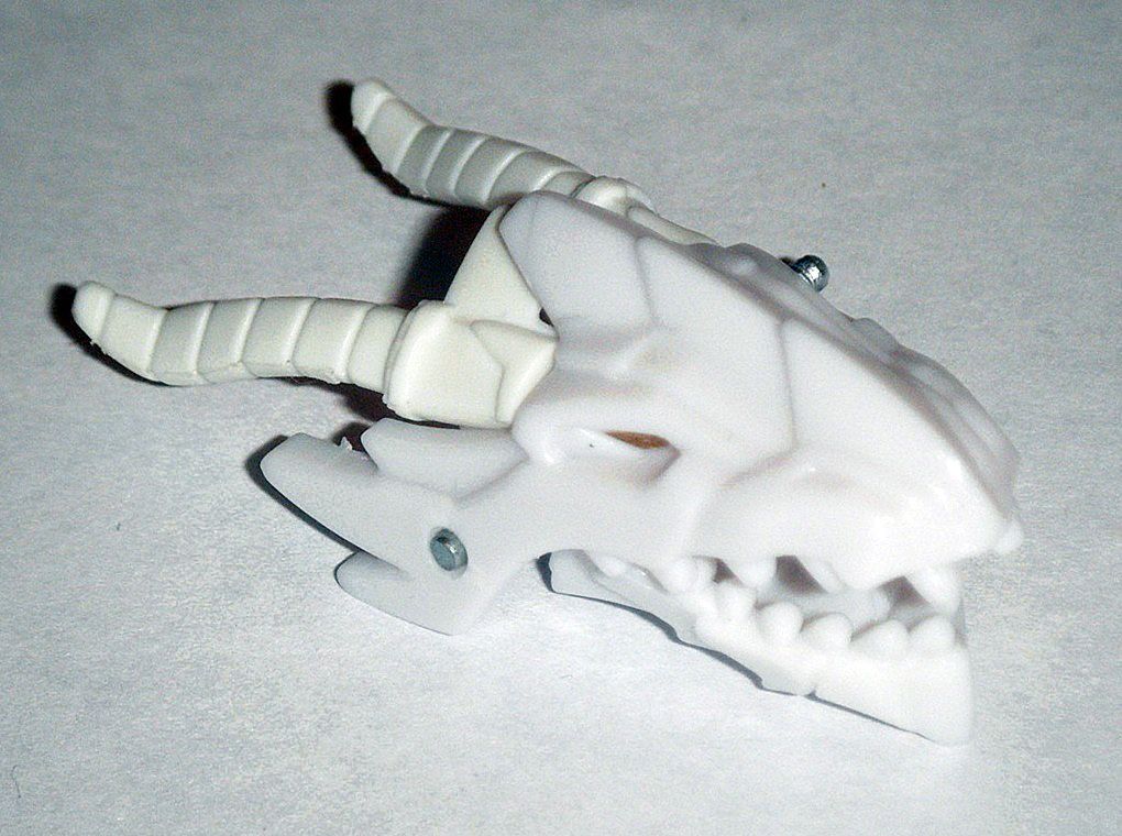
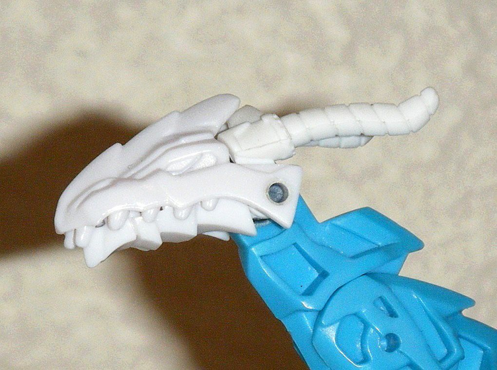
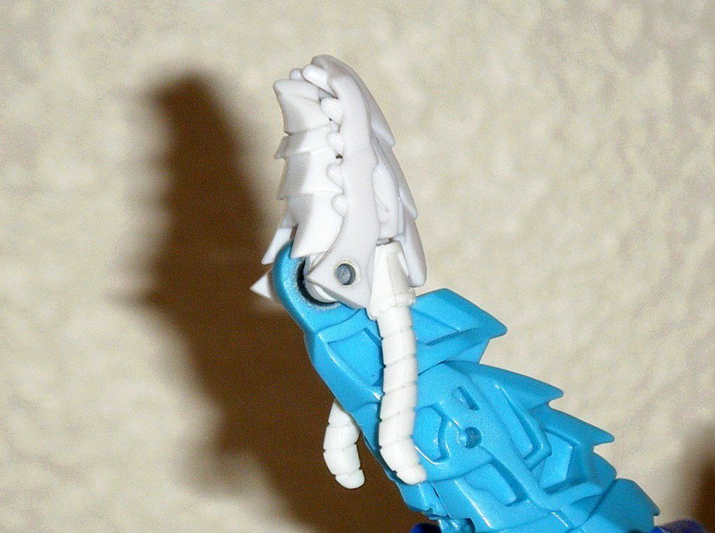
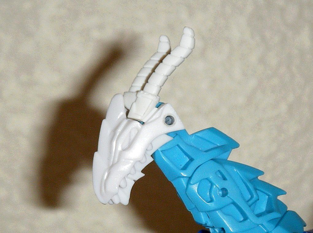
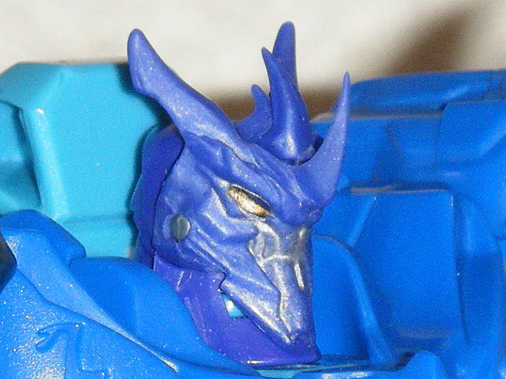
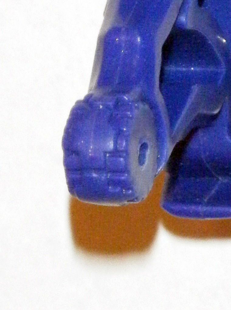
09) Mass at back of lower jaw teeth was sanded down and polished:
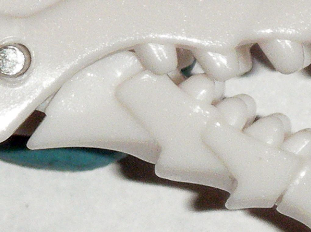
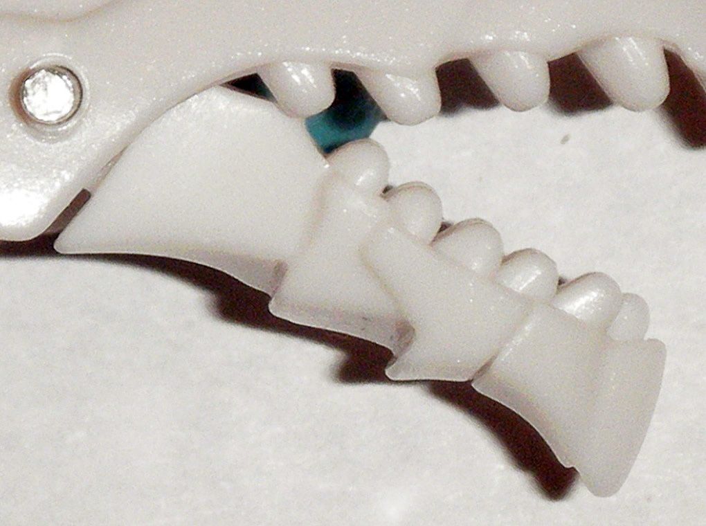
10) Tooth at front of lower jaw was removed:
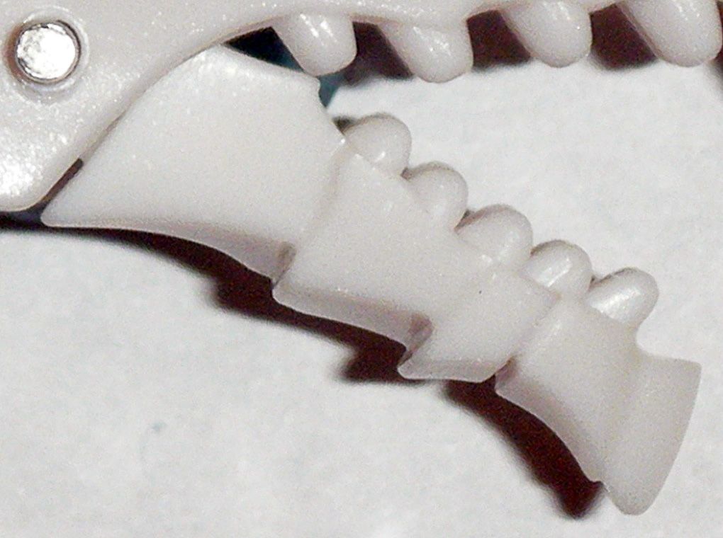
11) Left and right sides of inner upper jaw were carefully sanded down and polished:
12) Now the mouth can fully close shut:

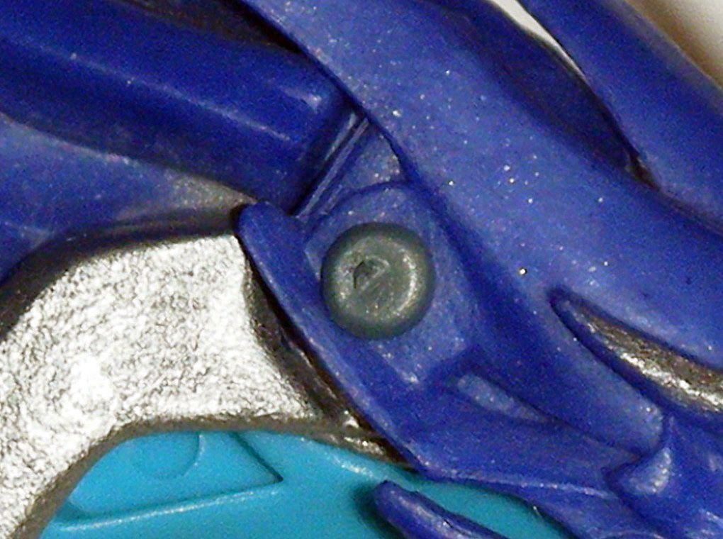
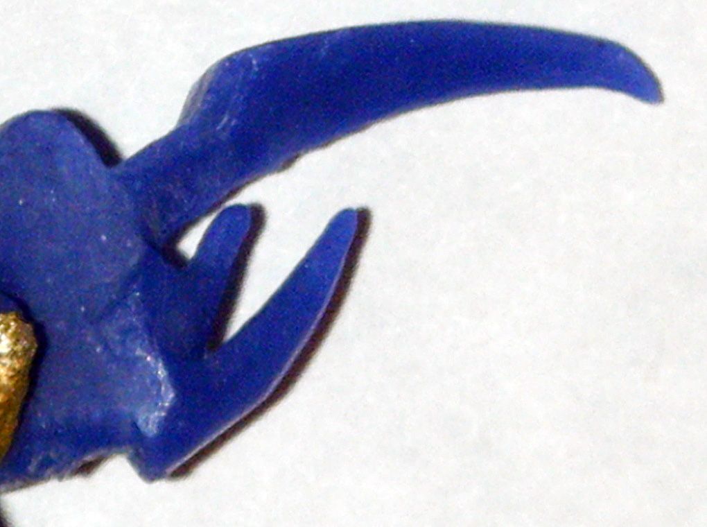
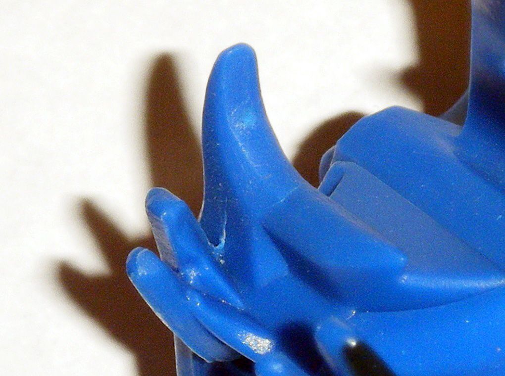
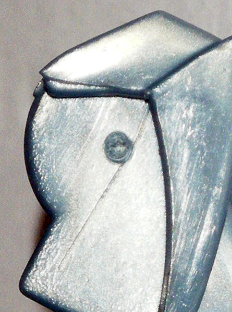
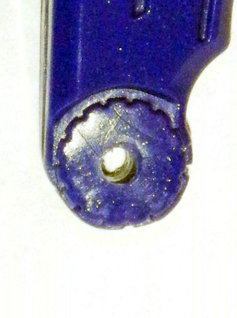
13) Cheek “horns” were removed:
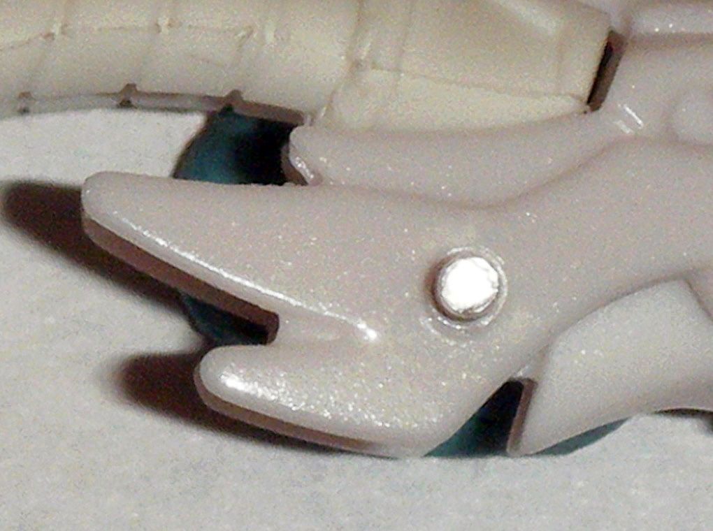
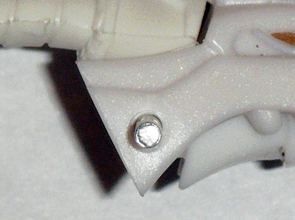
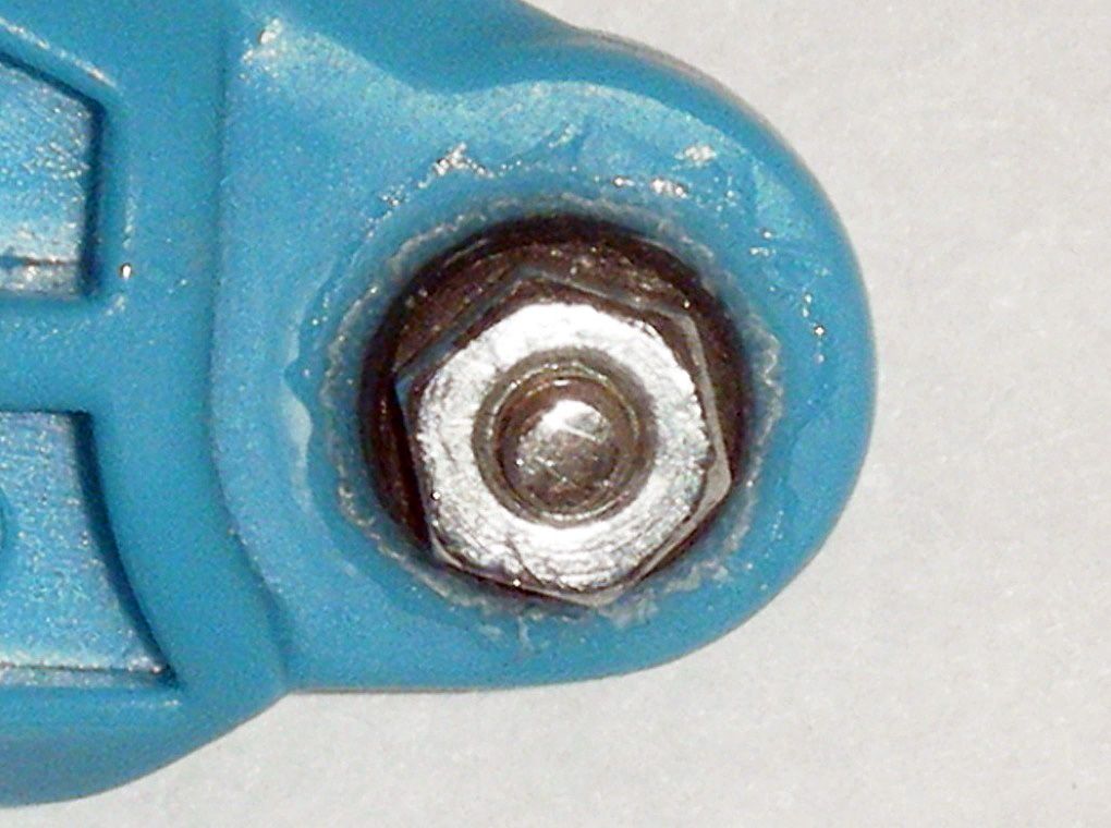
14) Left and right rivet holes on lower jaw were carefully widened with an
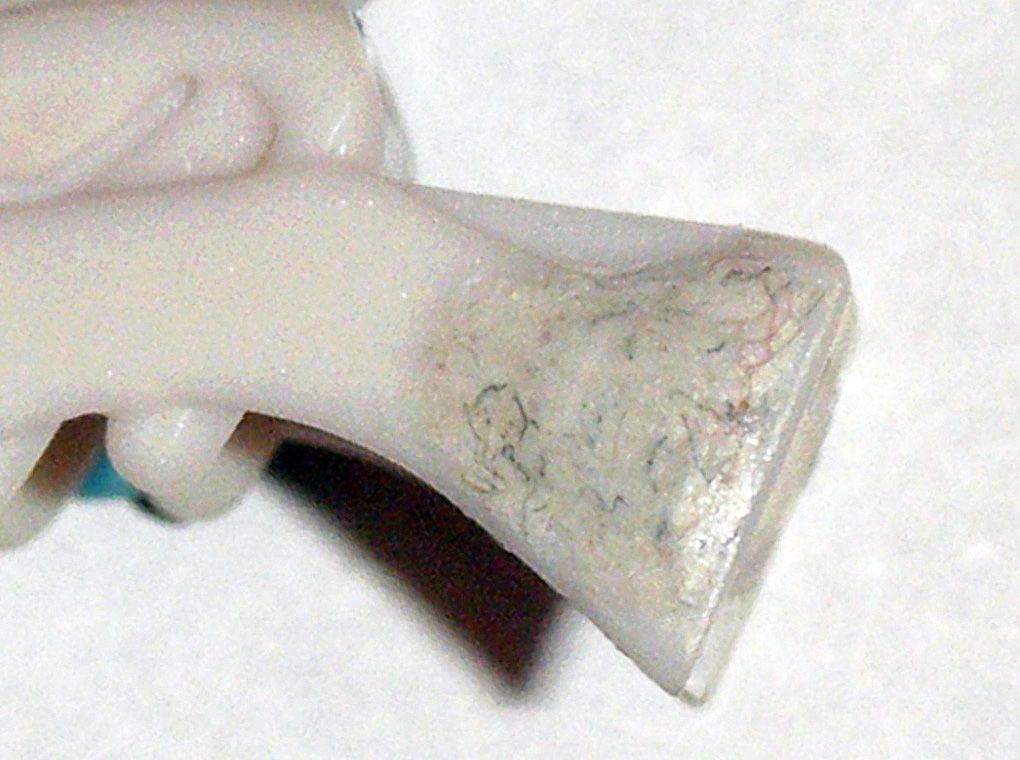
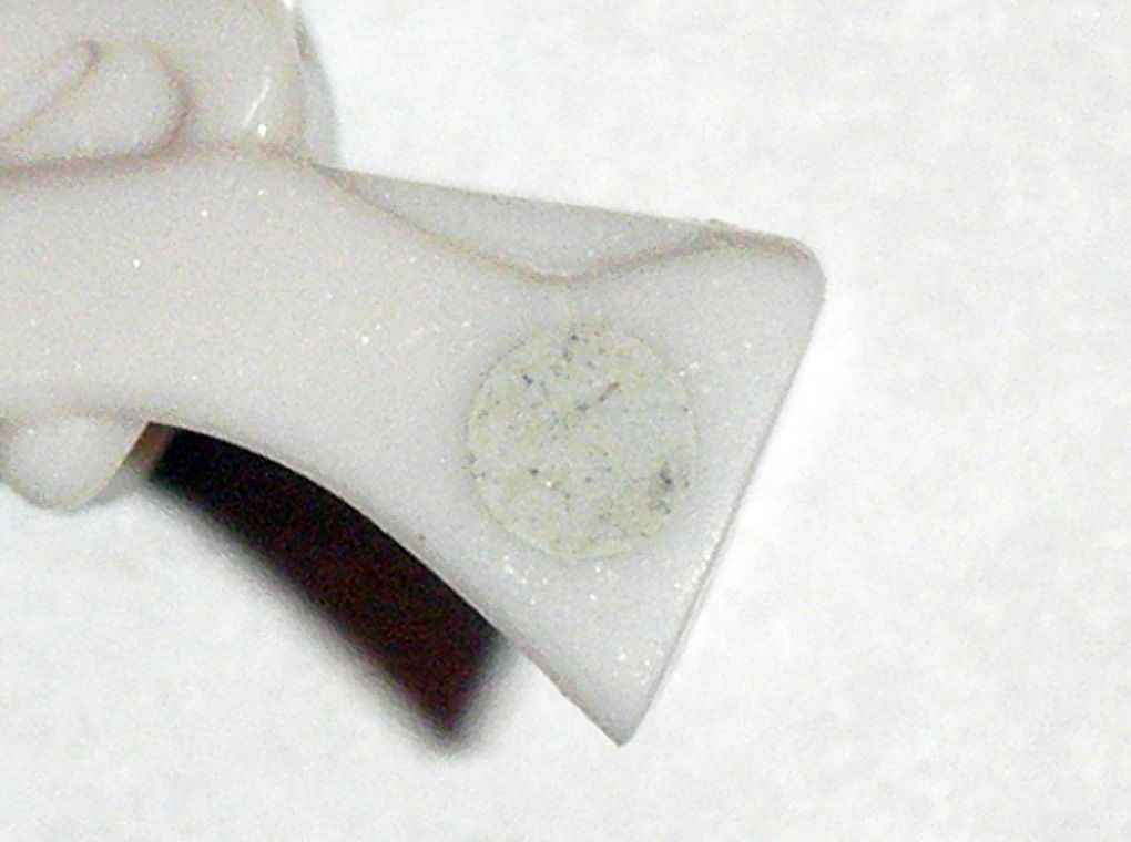
ACE 5/64” drill bit at low speed:
15) Throat area of lower jaw was widened enough to fit onto the modified head mount area:
16) Left and right rivet holes of upper jaw were carefully widened with an
ACE 5/64” drill bit at low speed:
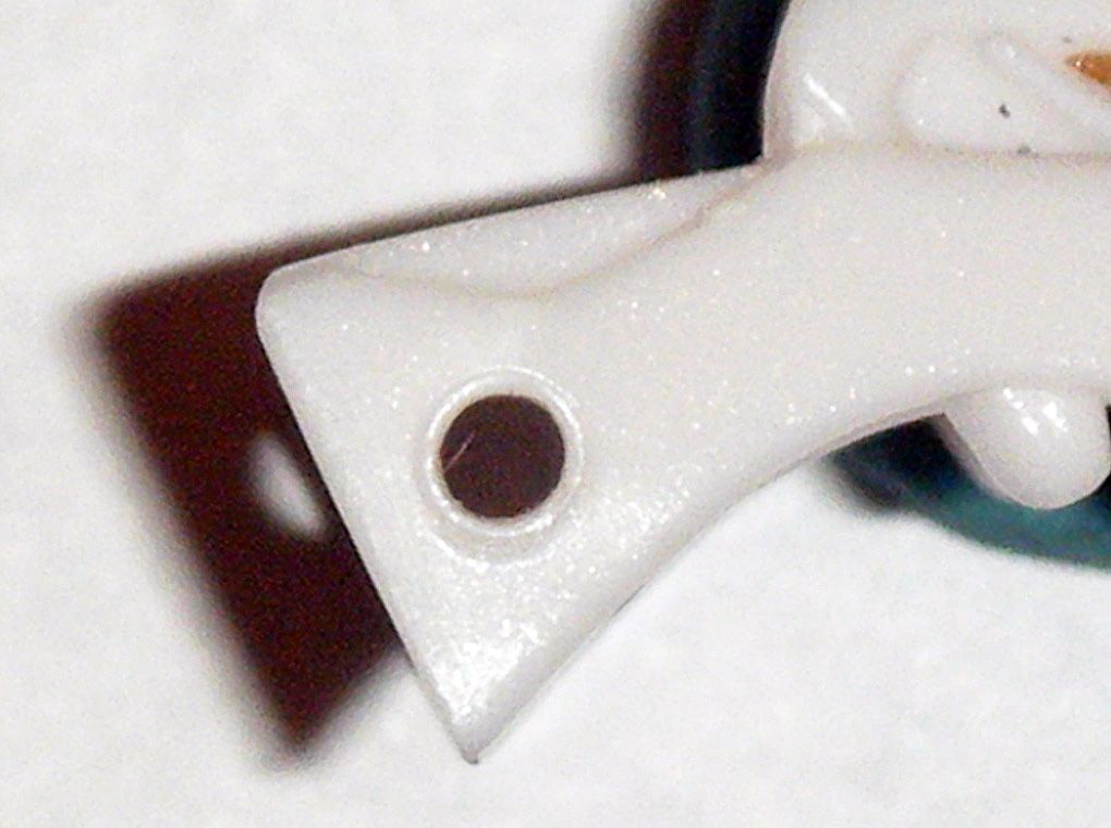
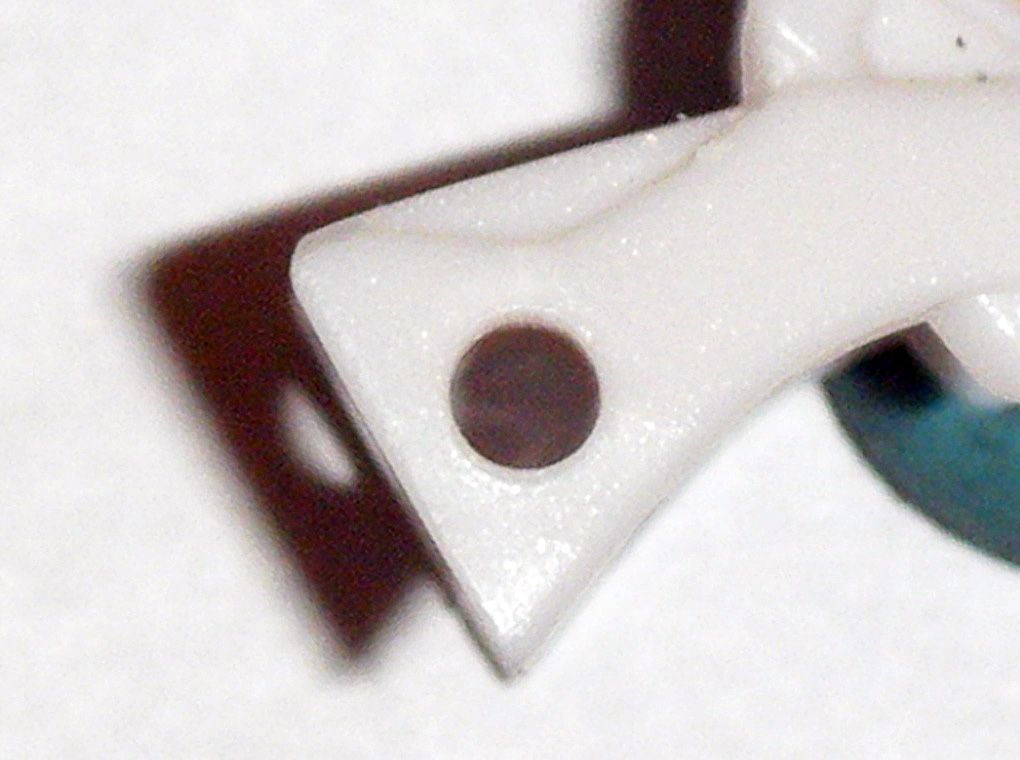
17) Head was submerged in
91% Isopropyl Alcohol to remove gold paint app on eyes:
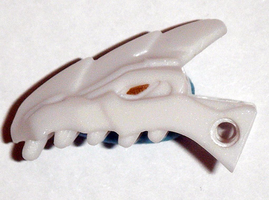
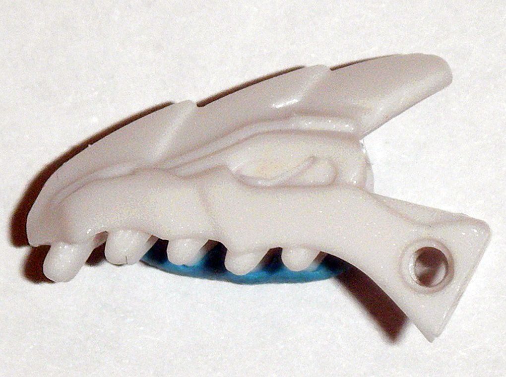
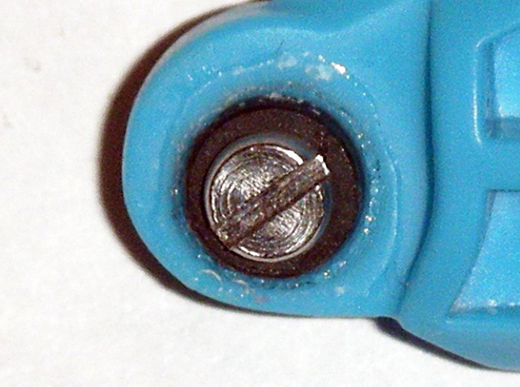
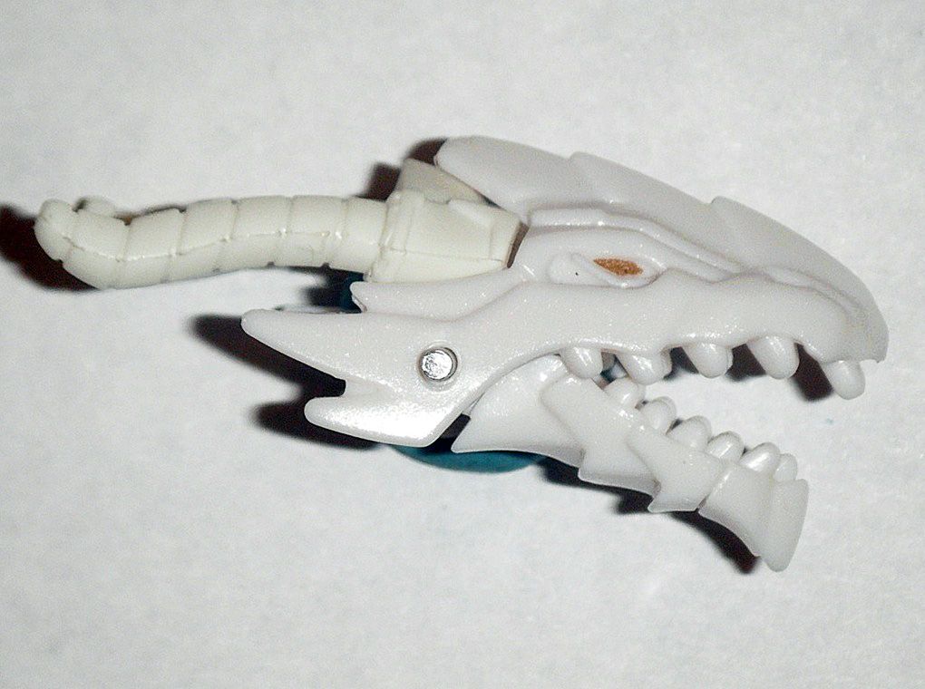
18) Applied
Epoxy Repair Putty over right rivet hole of upper jaw and let fully cure for a week after application:
19) After said week, area was carefully sanded down flat and polished:
20) Used spike to apply a small hole on center of cured
Epoxy Repair Putty over right rivet hole of upper jaw in order to carefully drill hole through at low speed using, in order
Dremel 1/32”,
3/64”,
1/16” drill bits,
ACE 5/64” drill bit:
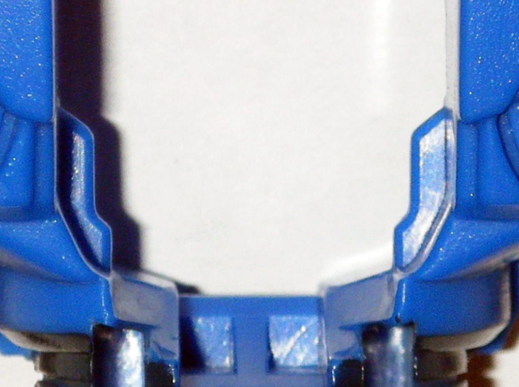
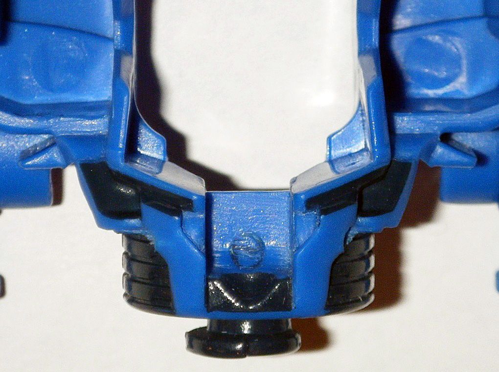
21) Cut and sanded down upper area inside “dragon horns” part:
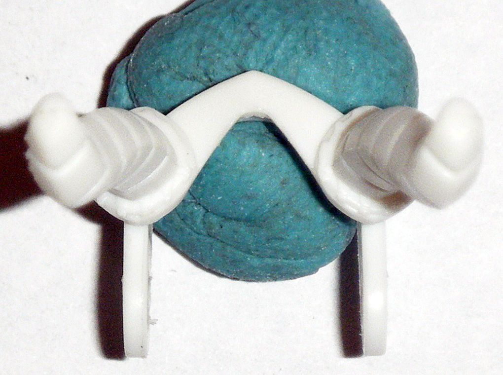
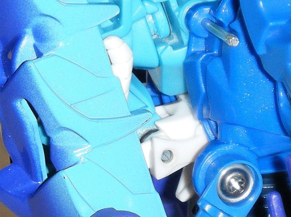
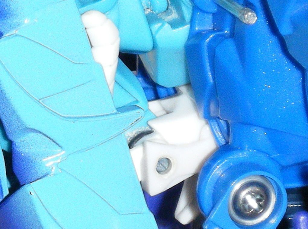
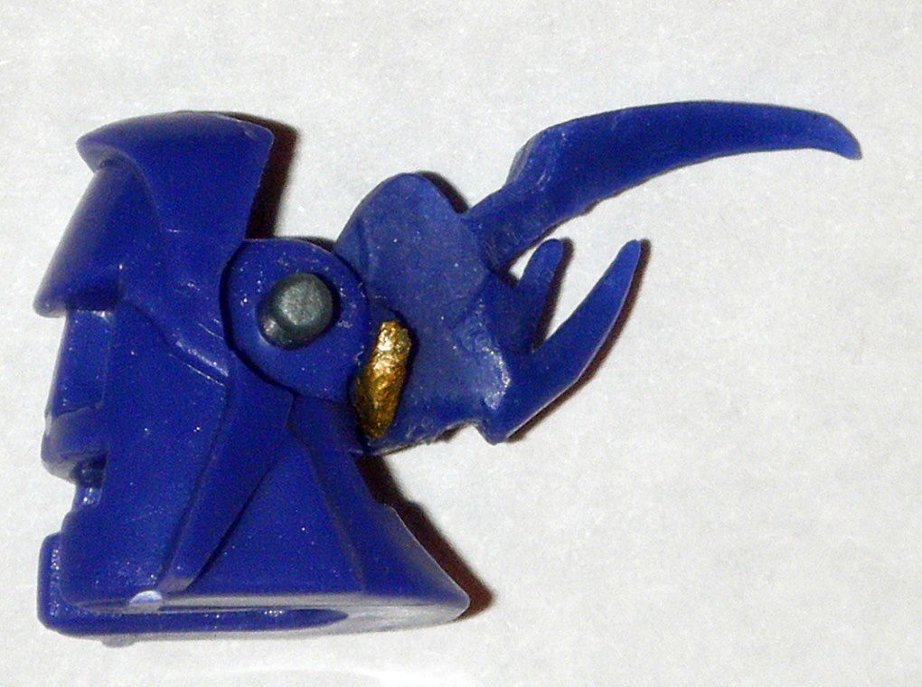
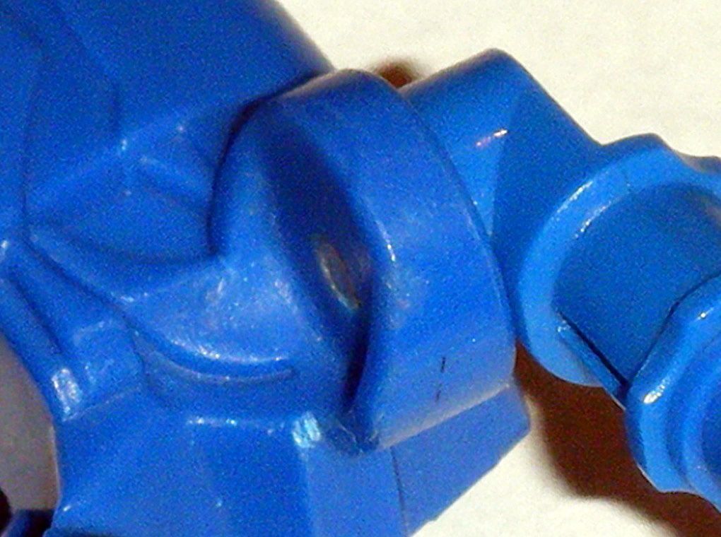
22) Attached modified alt mode head with gray plastic rivet from figure:
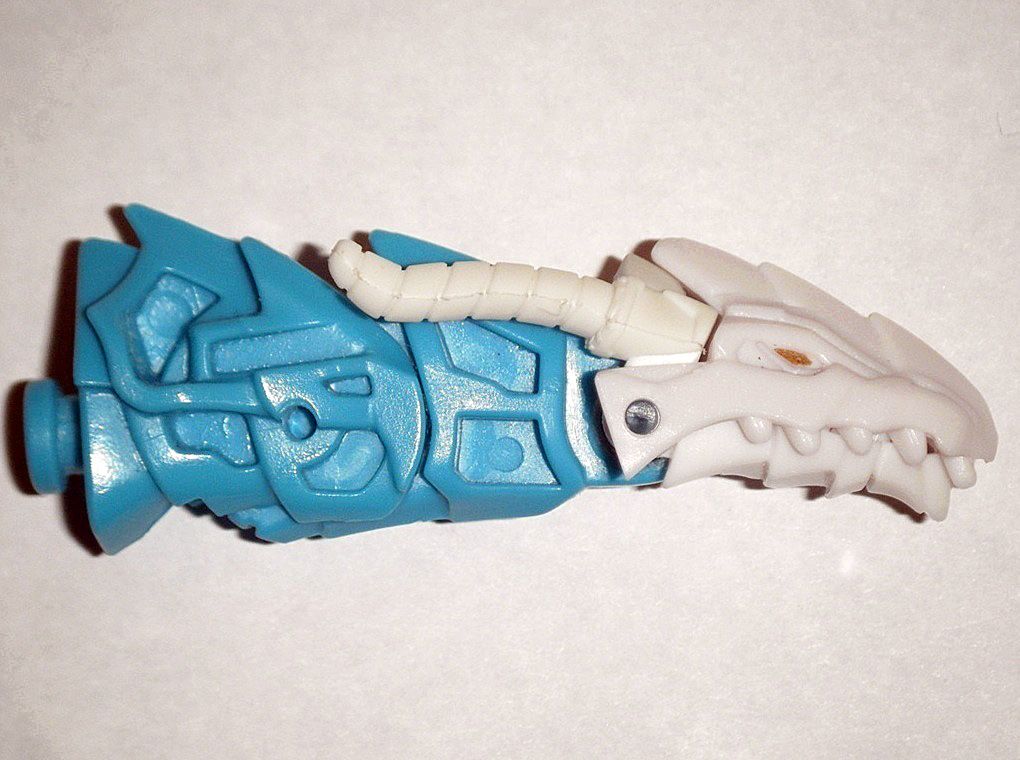
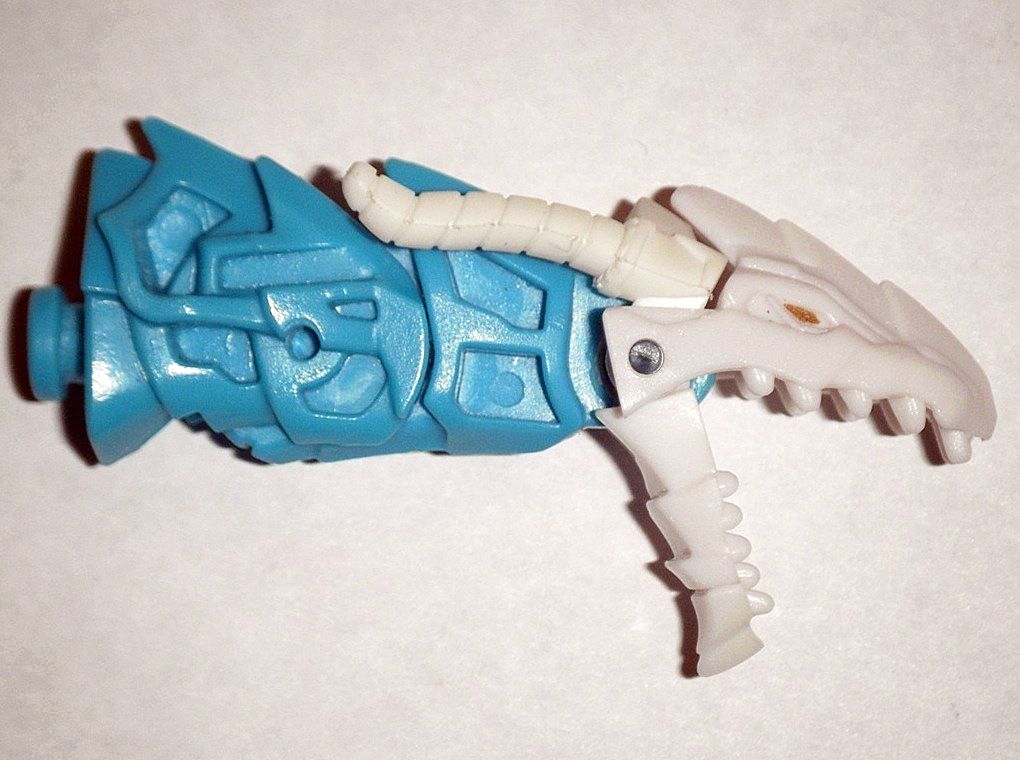
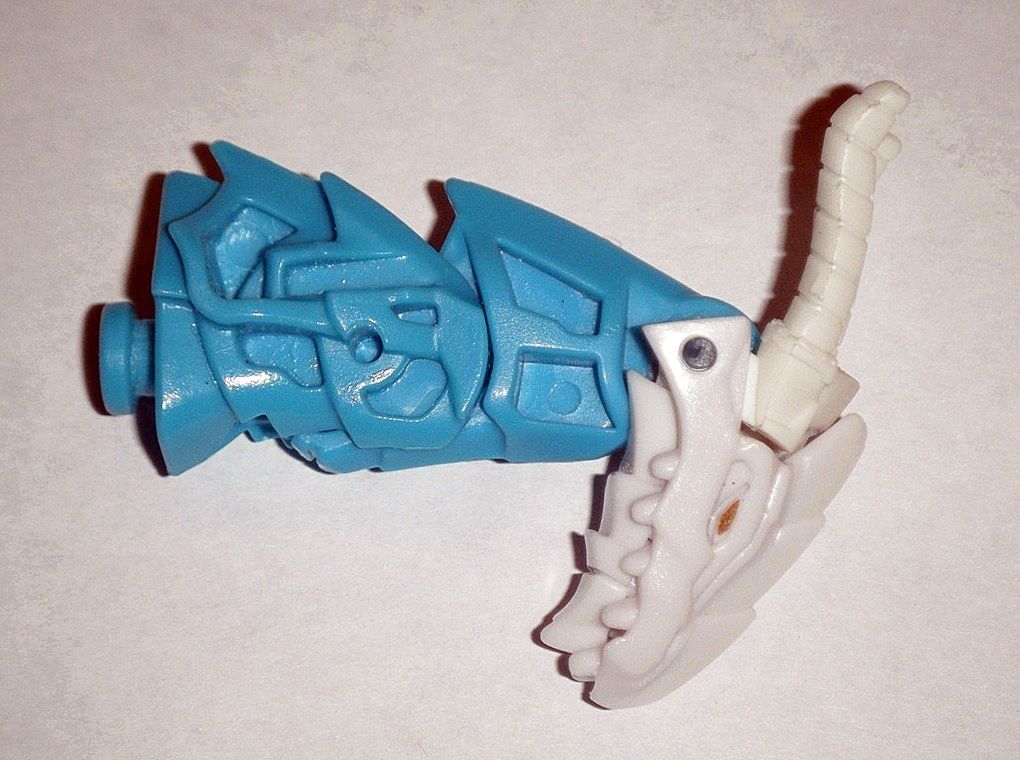
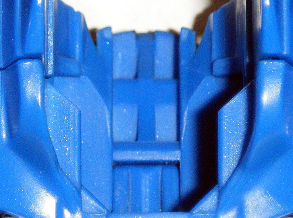
23) Alternate mode neck required additional cutting, sanding, and polishing down to fully accommodate the new, modified alternate mode head in alternate and robot mode:
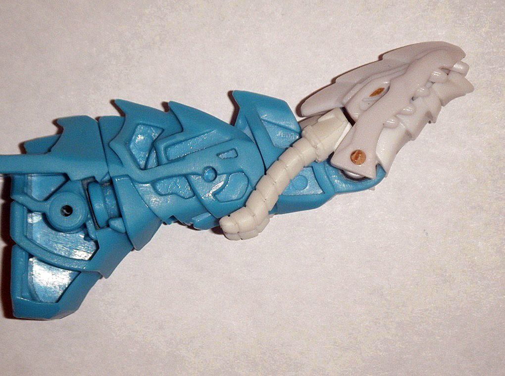
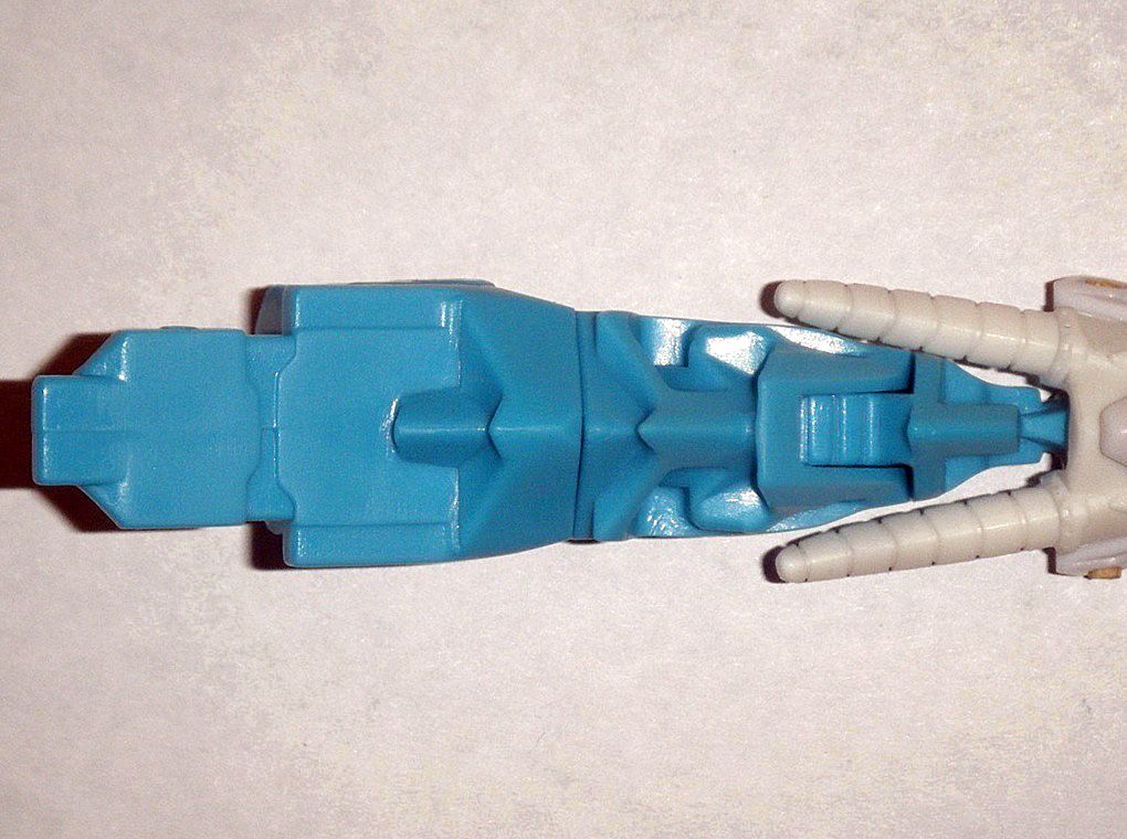
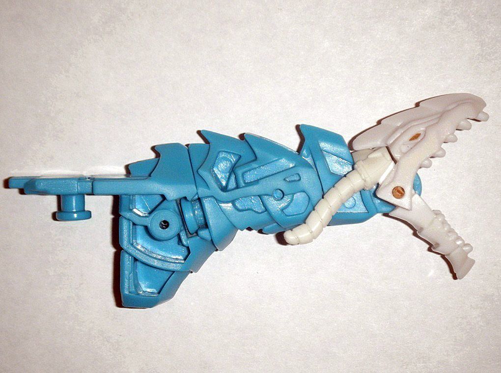
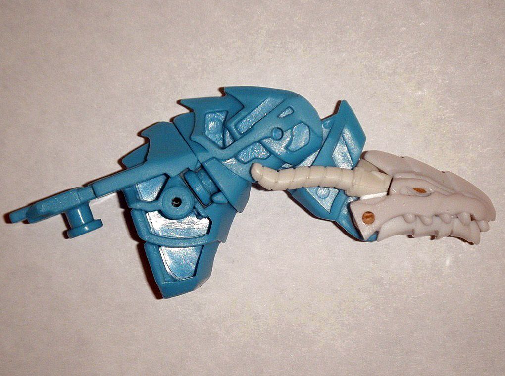
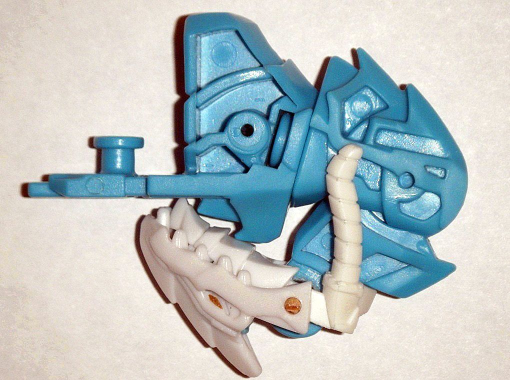
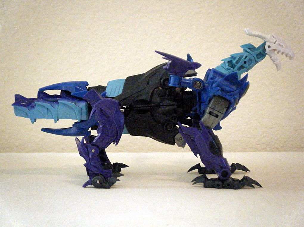
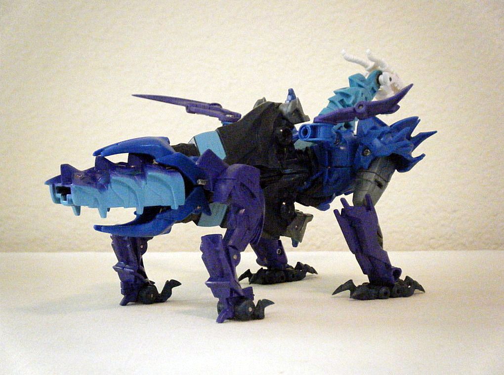
RESULT: the alternate mode head can move up and down with jaws that can open wide and fold/fit into the back of the robot mode.
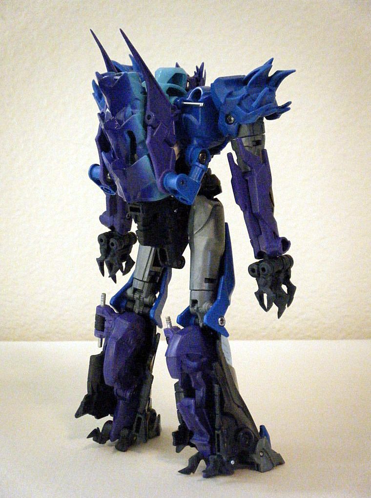
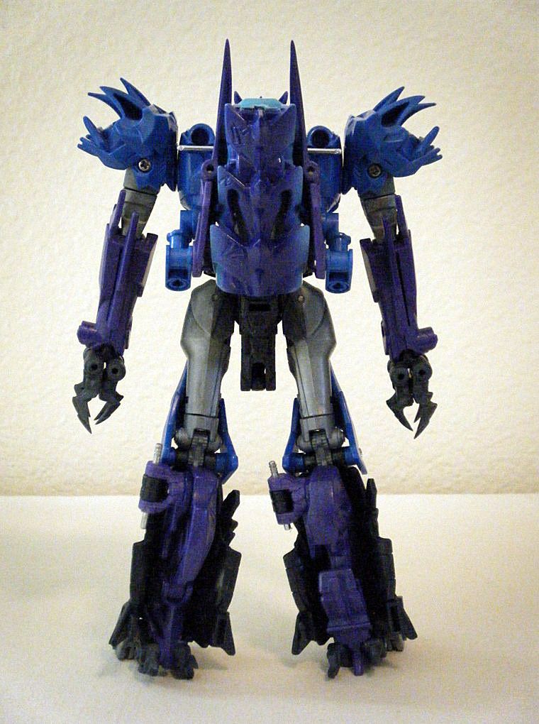
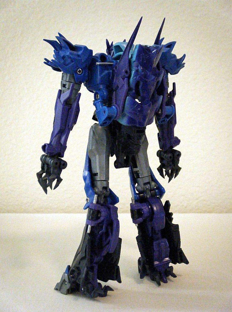
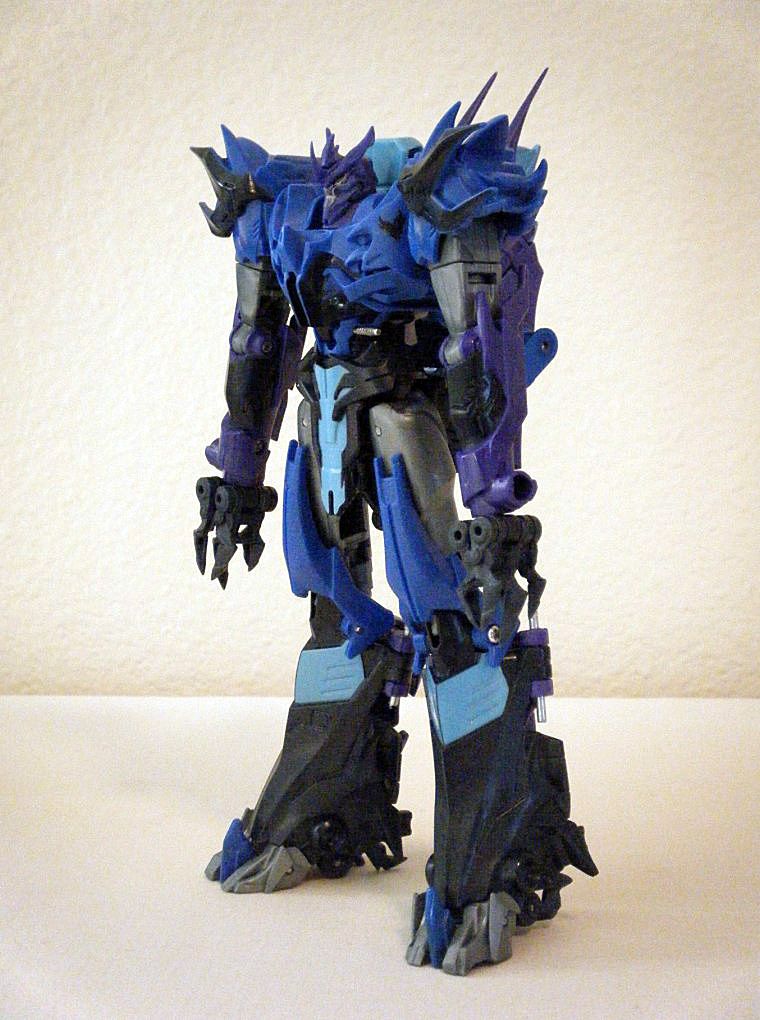
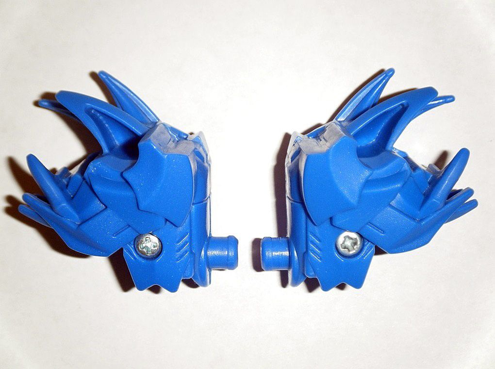
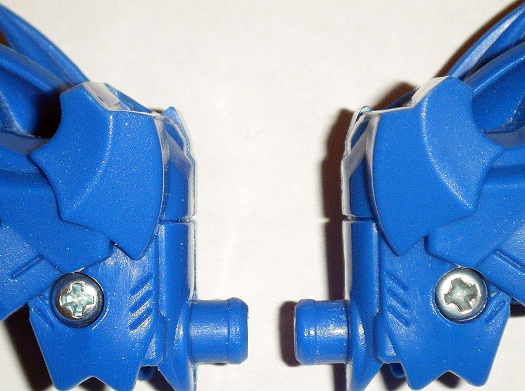
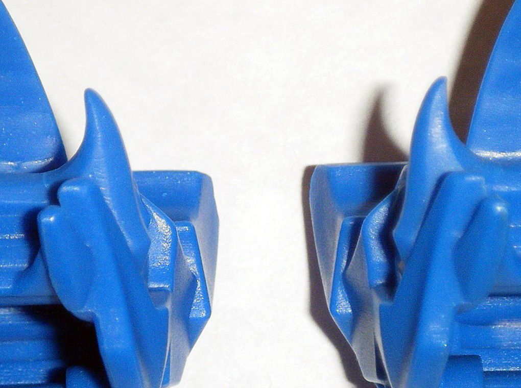
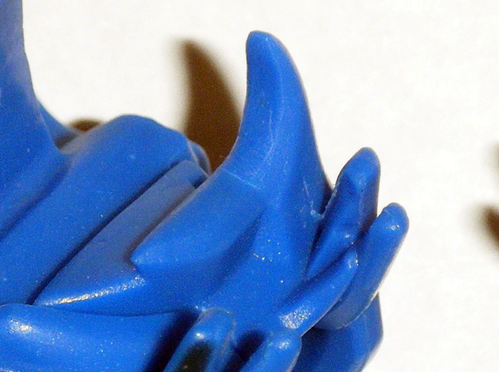
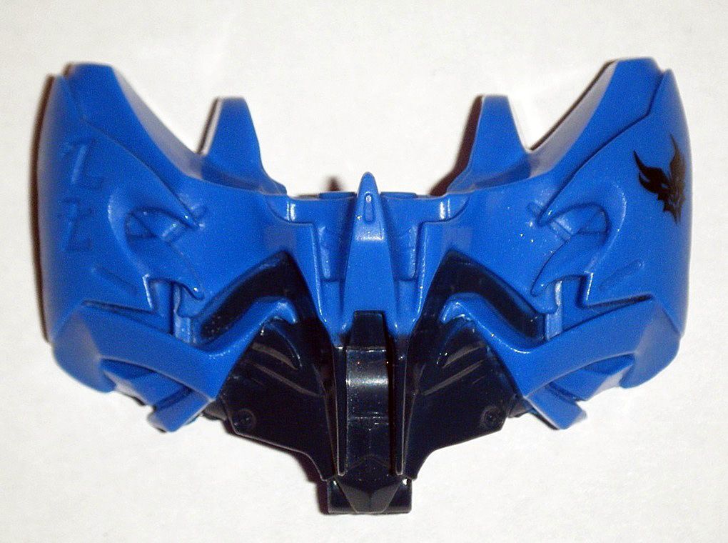
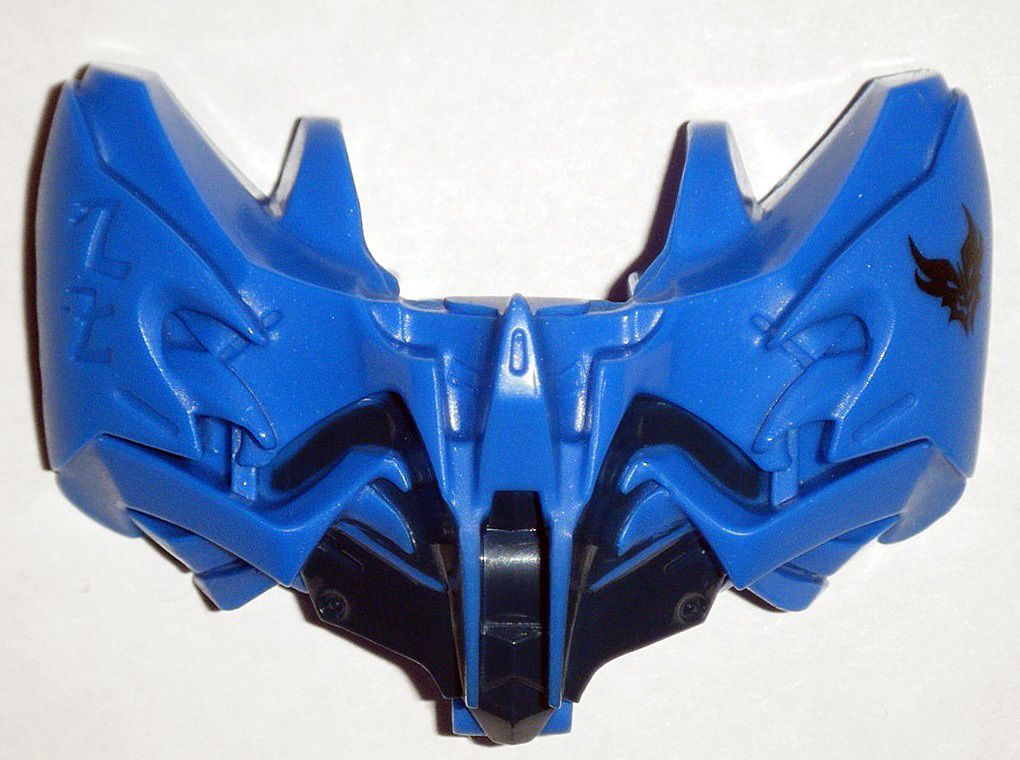
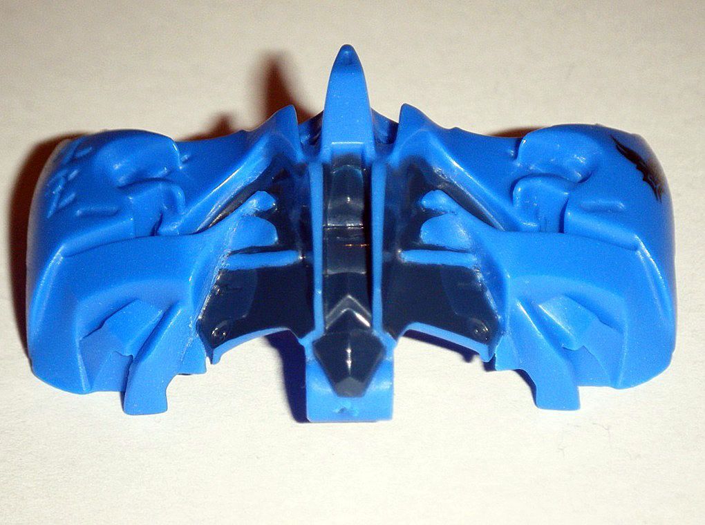
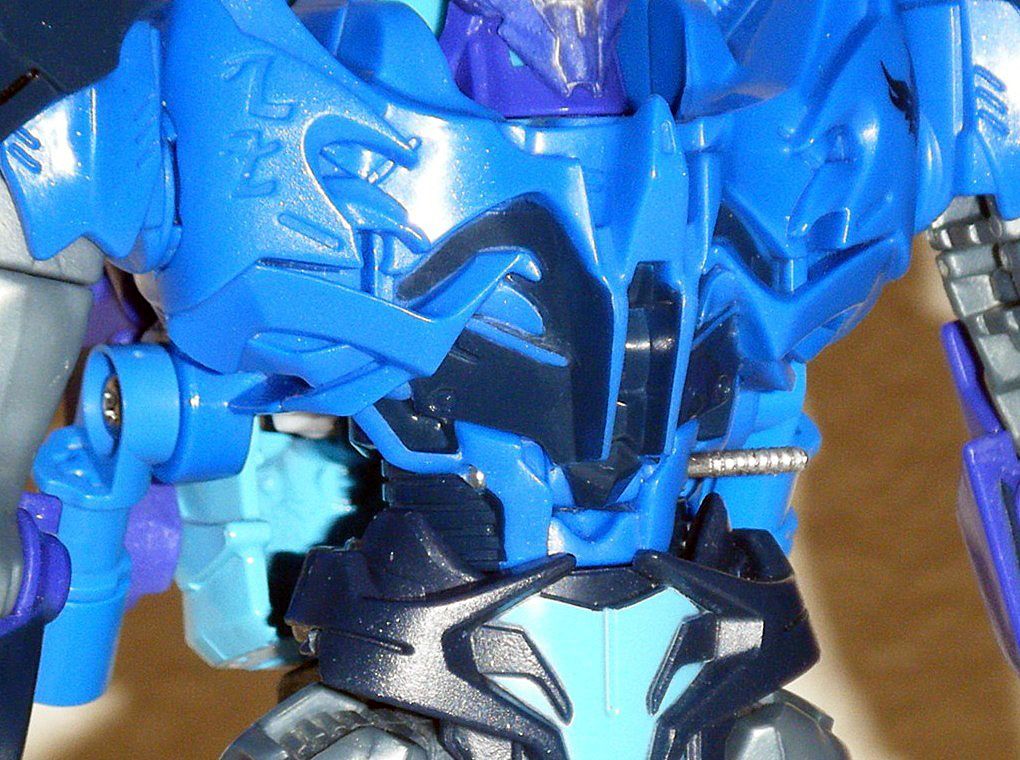
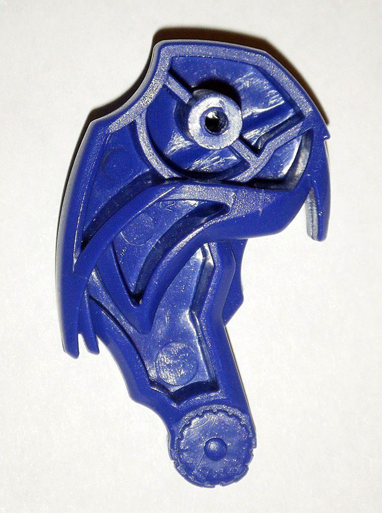
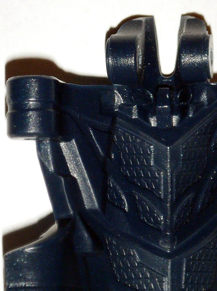
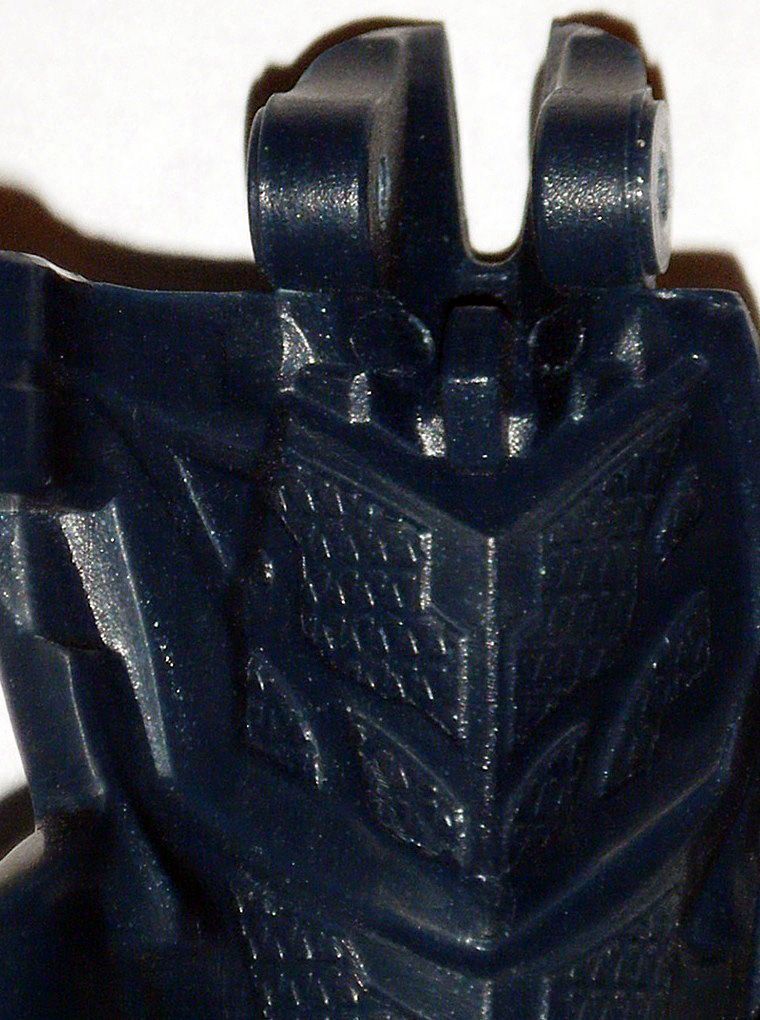
 B) ROBOT MODE HEAD:
In an effort to make
Dreadnought look less like
Predaking in robot mode, certain parts of his robot mode head were modified and removed.
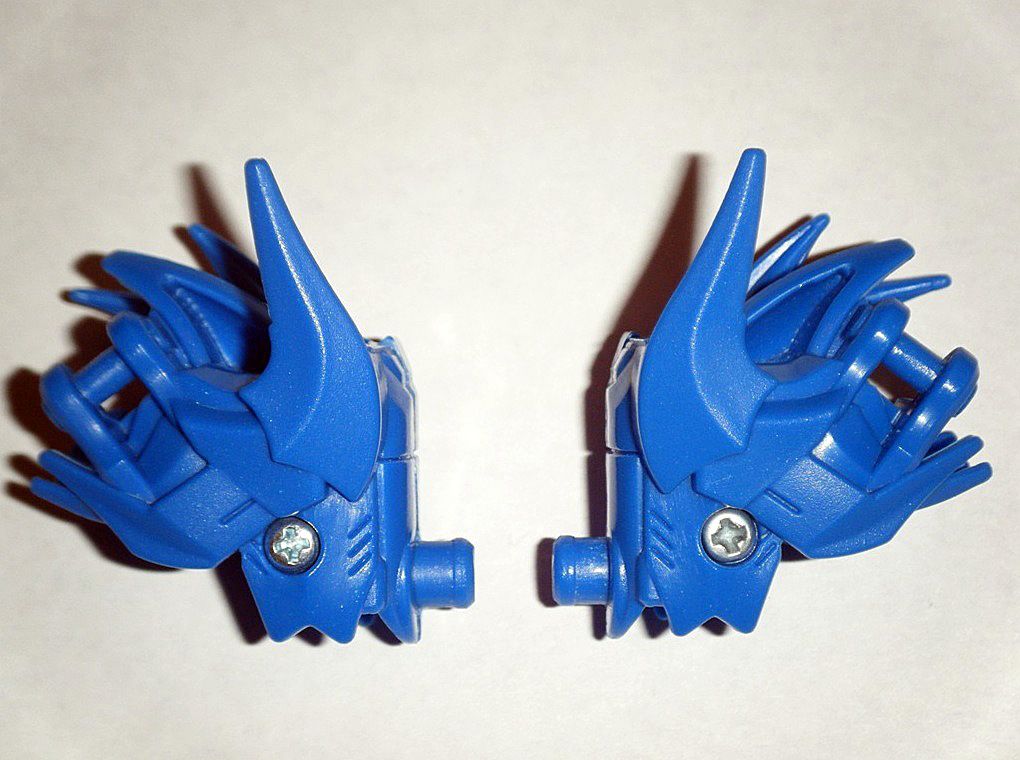
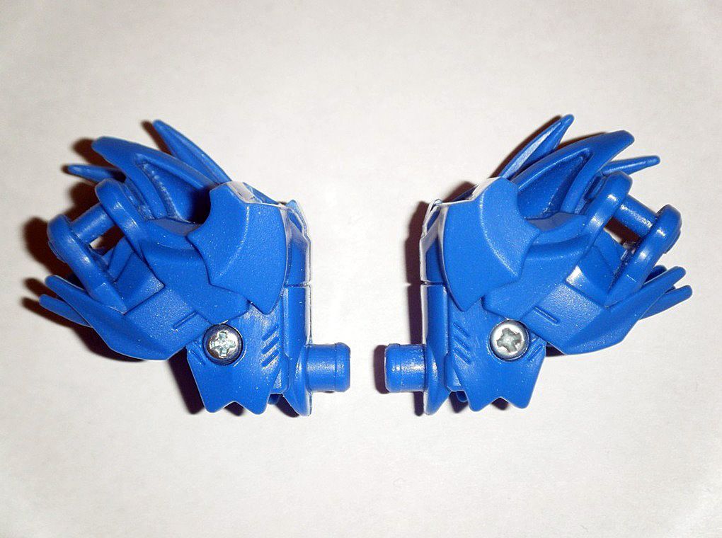
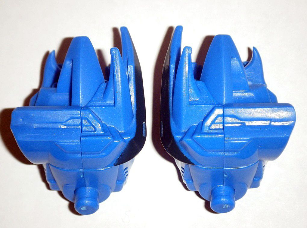
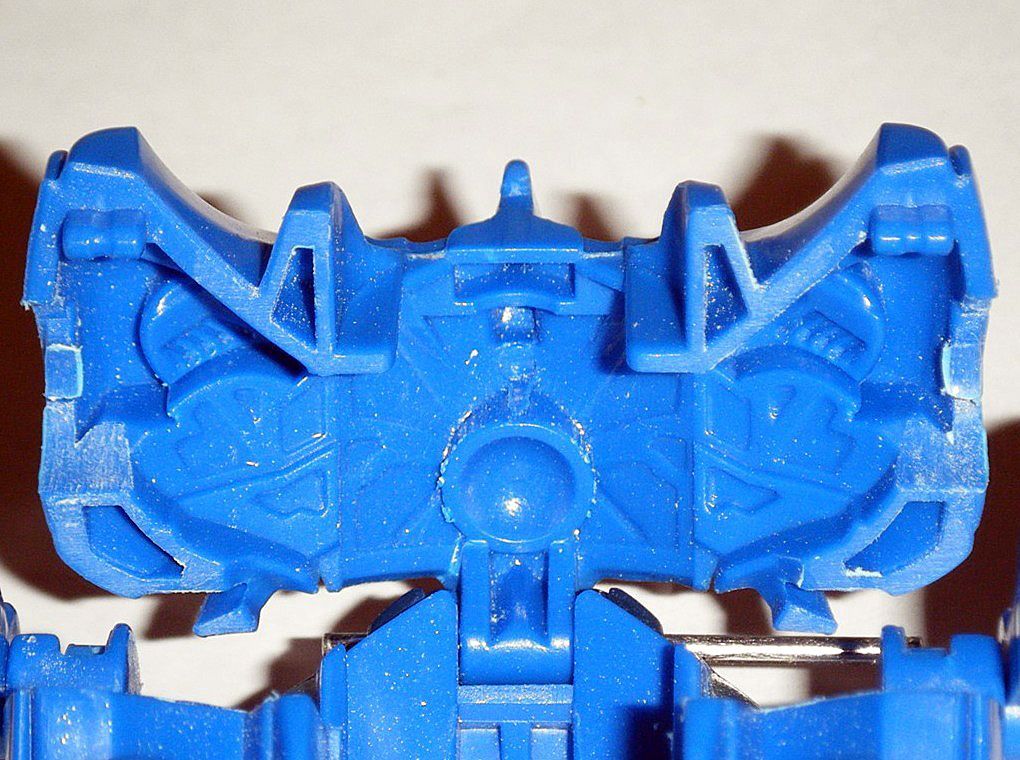
01) Robot mode scalp & face were separated:
02) Lower horns on back of face were removed:
03) Long horn on top of scalp was removed:
04) Head was reattached to scalp:
RESULT: Robot mode head that looks a bit
Galvatron, but distinctive in its own way.
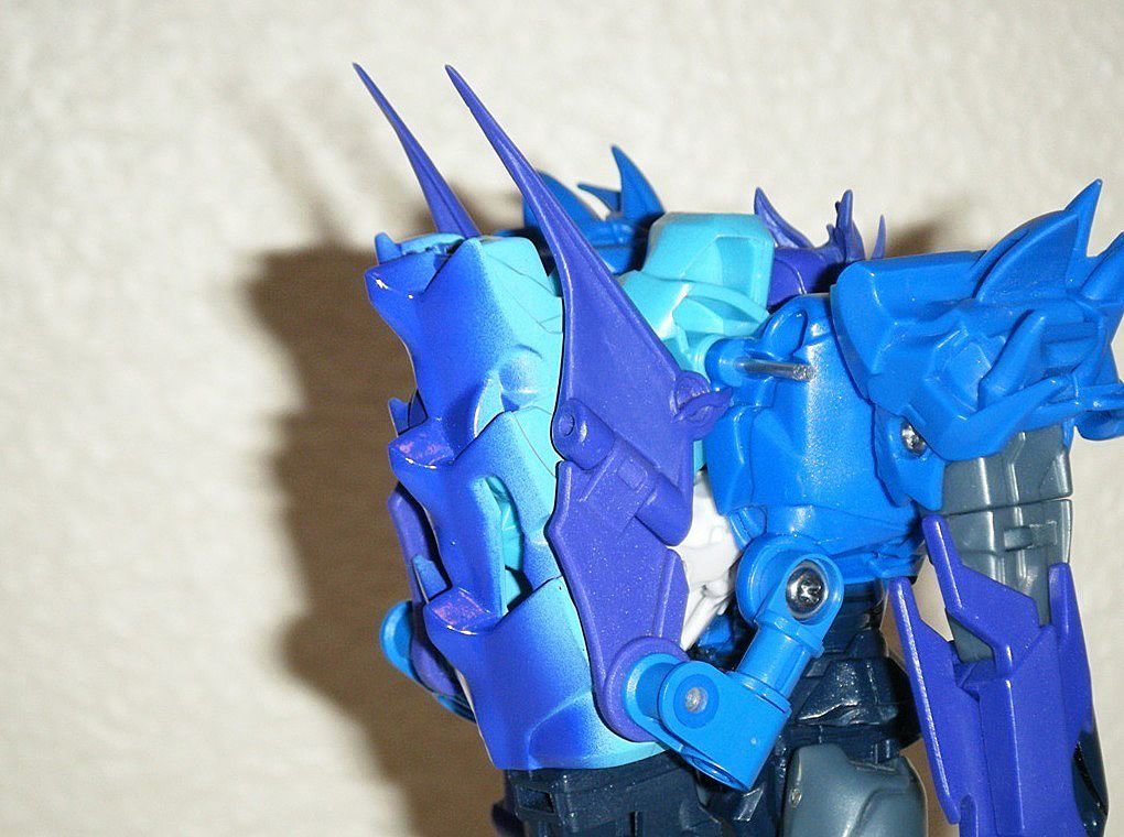
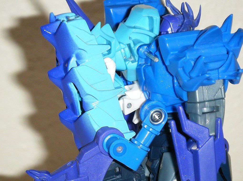
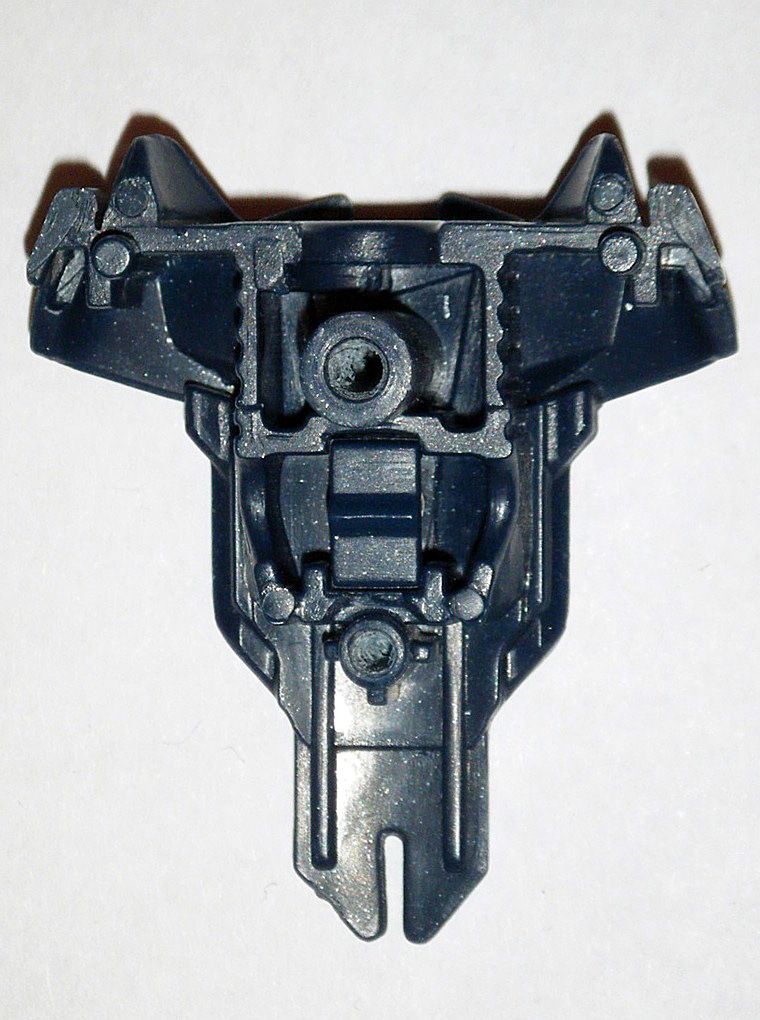
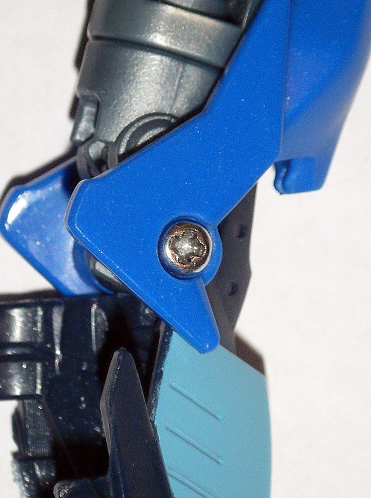
 C) ROBOT MODE SHOULDERS:
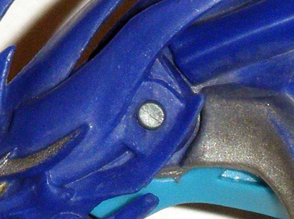
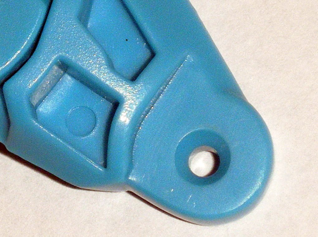
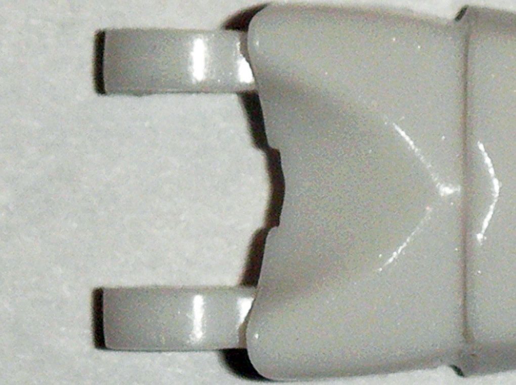
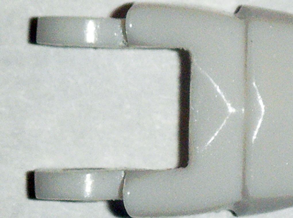
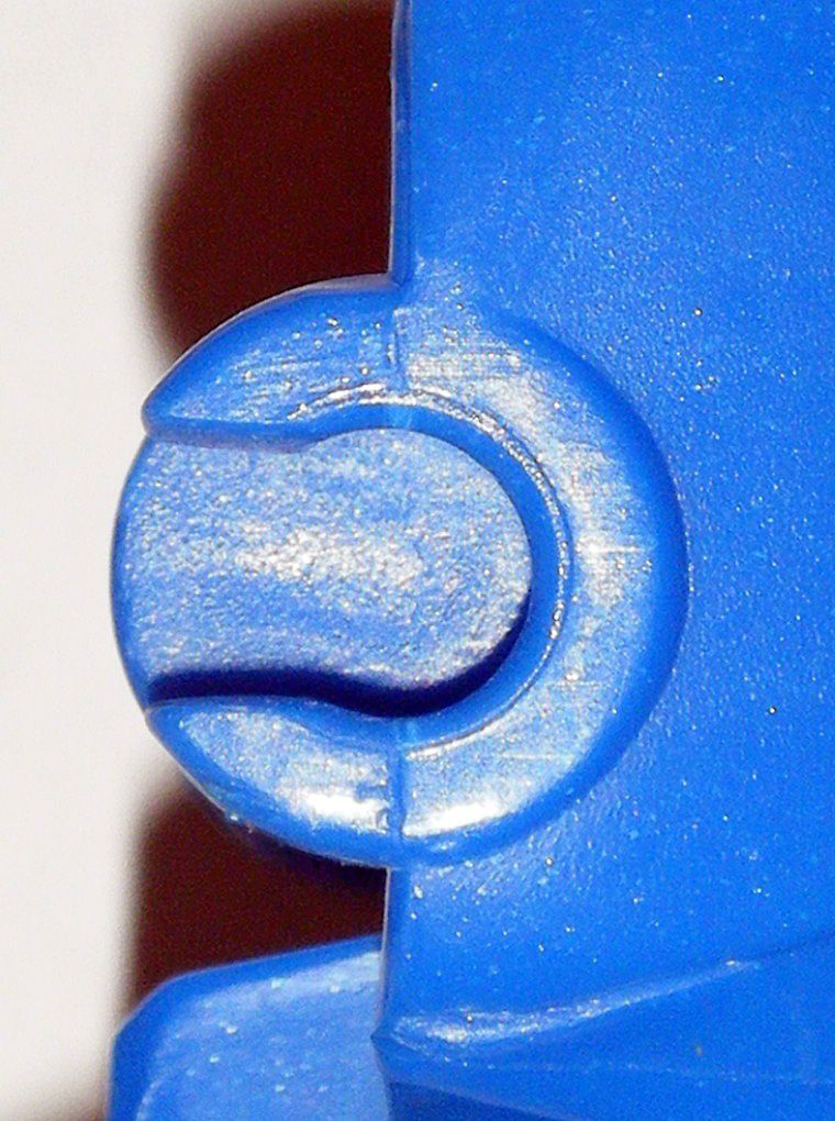
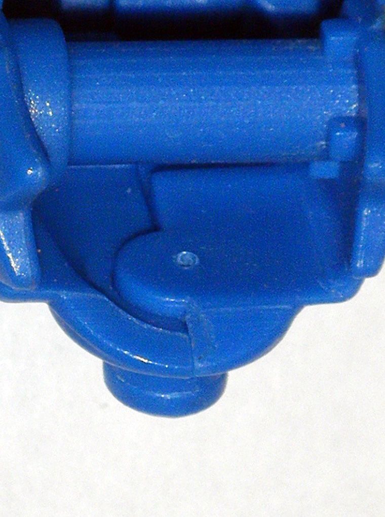
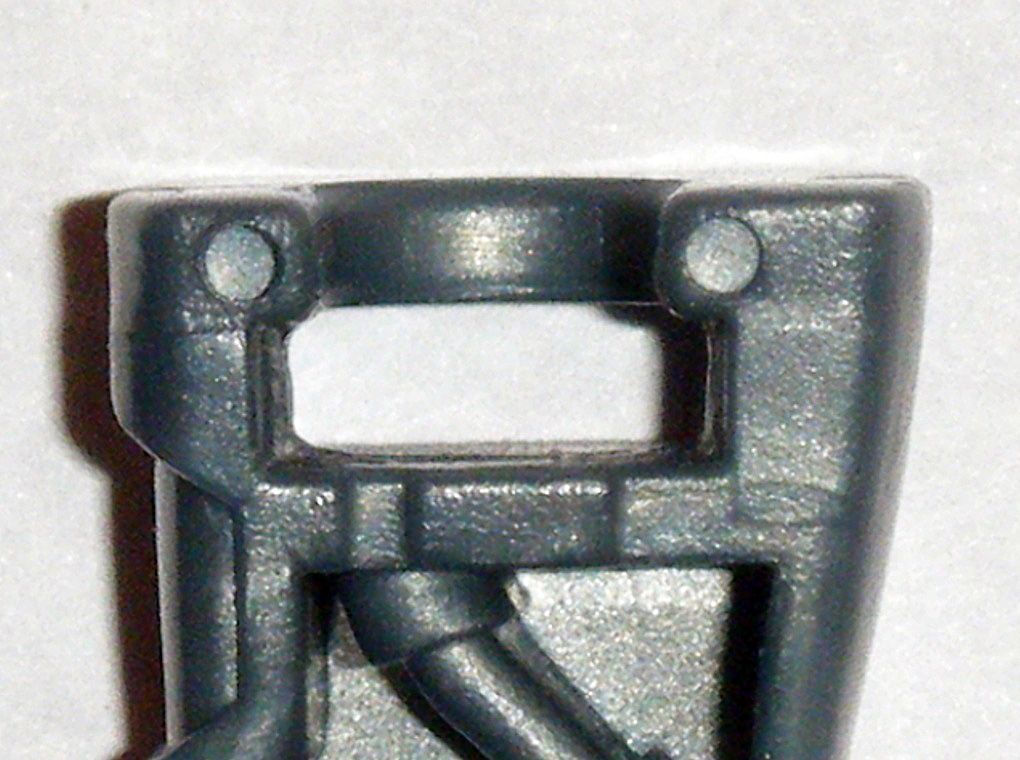
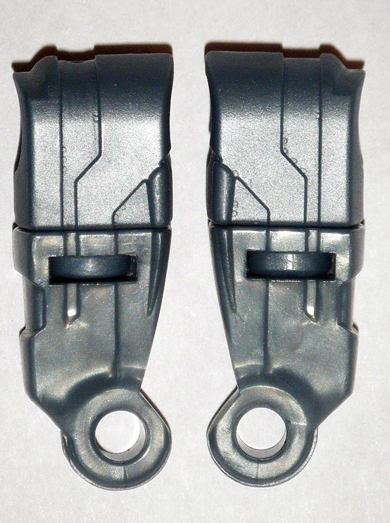
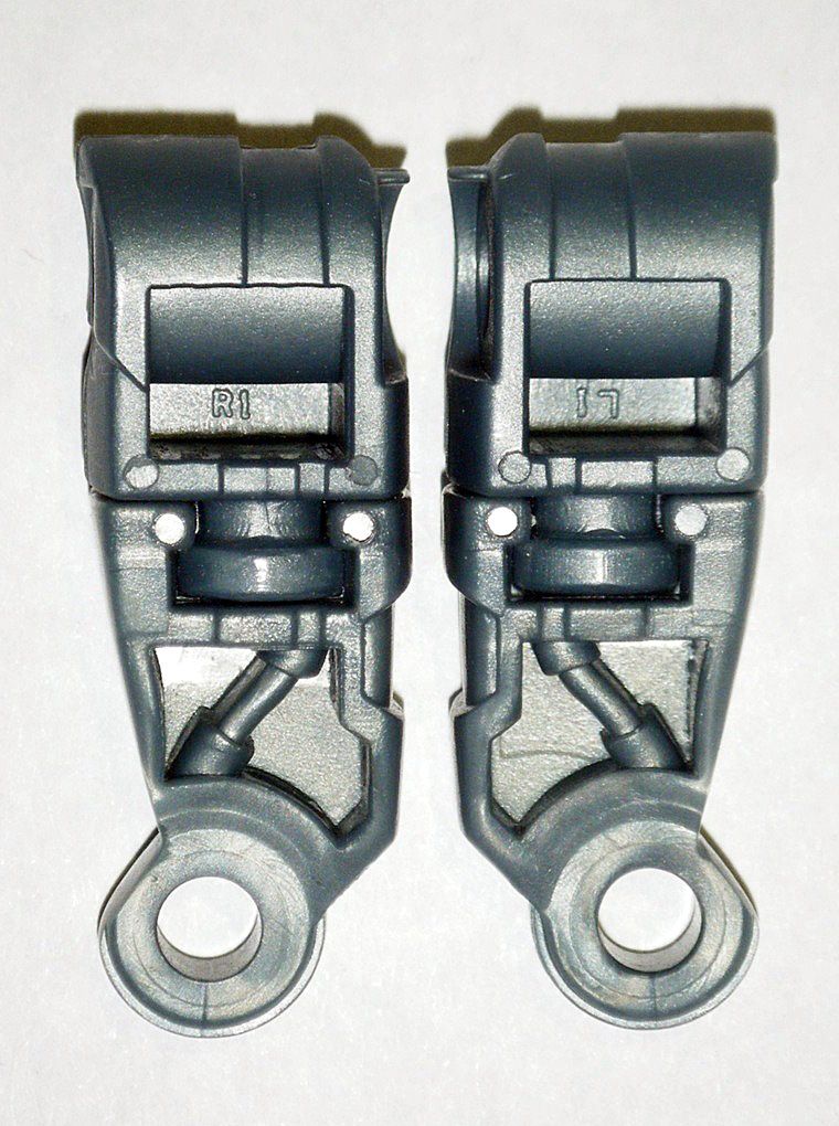
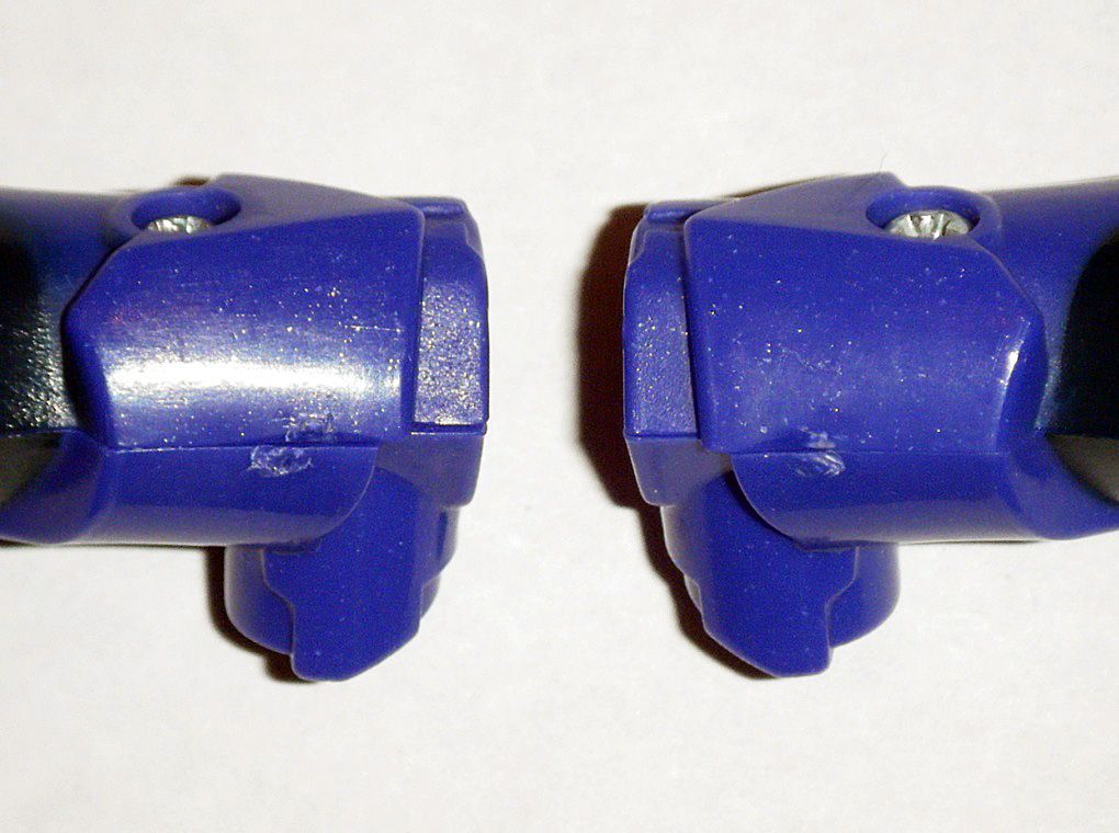
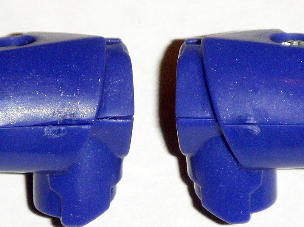
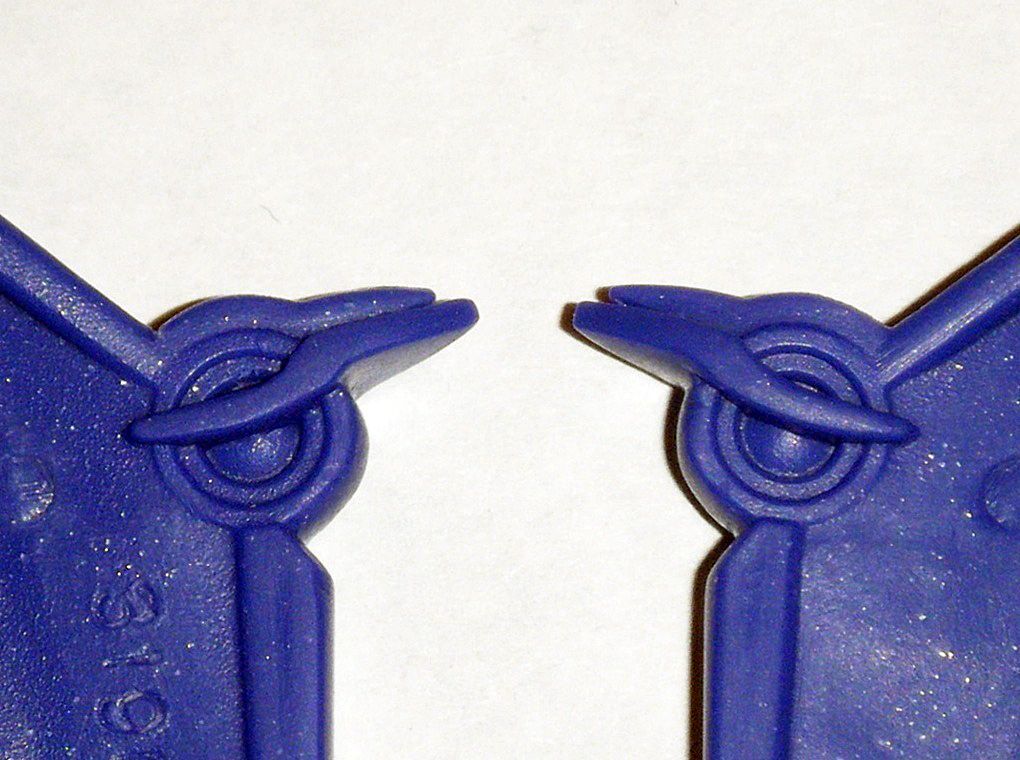
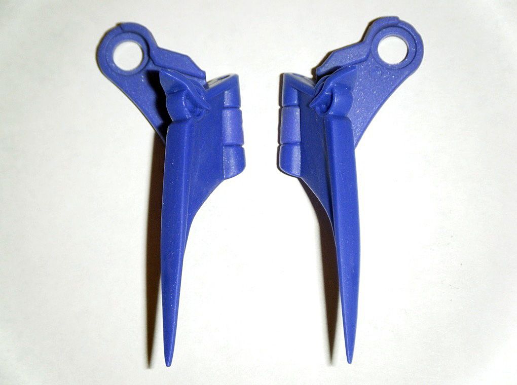
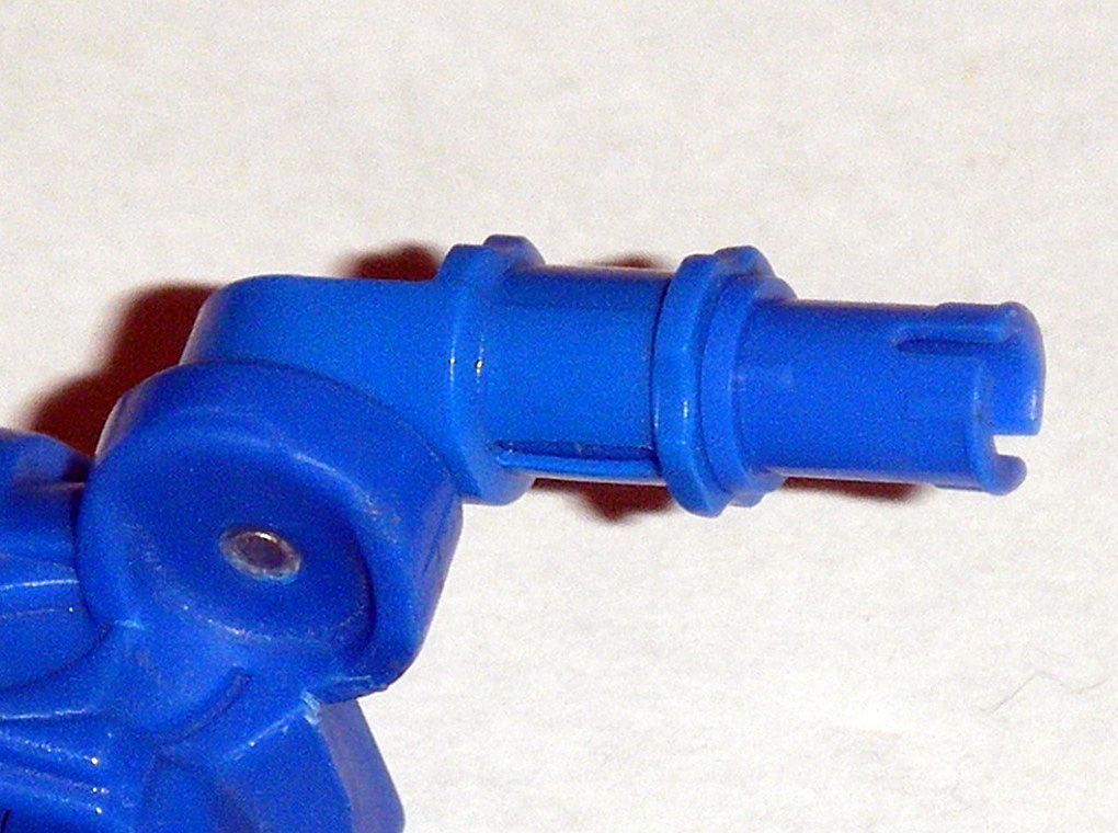
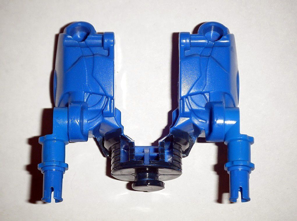
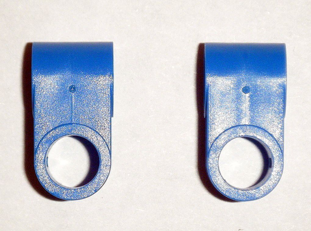
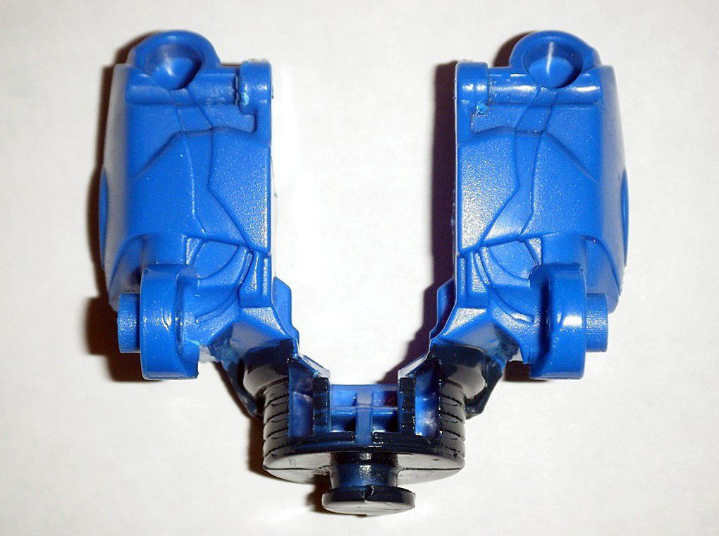
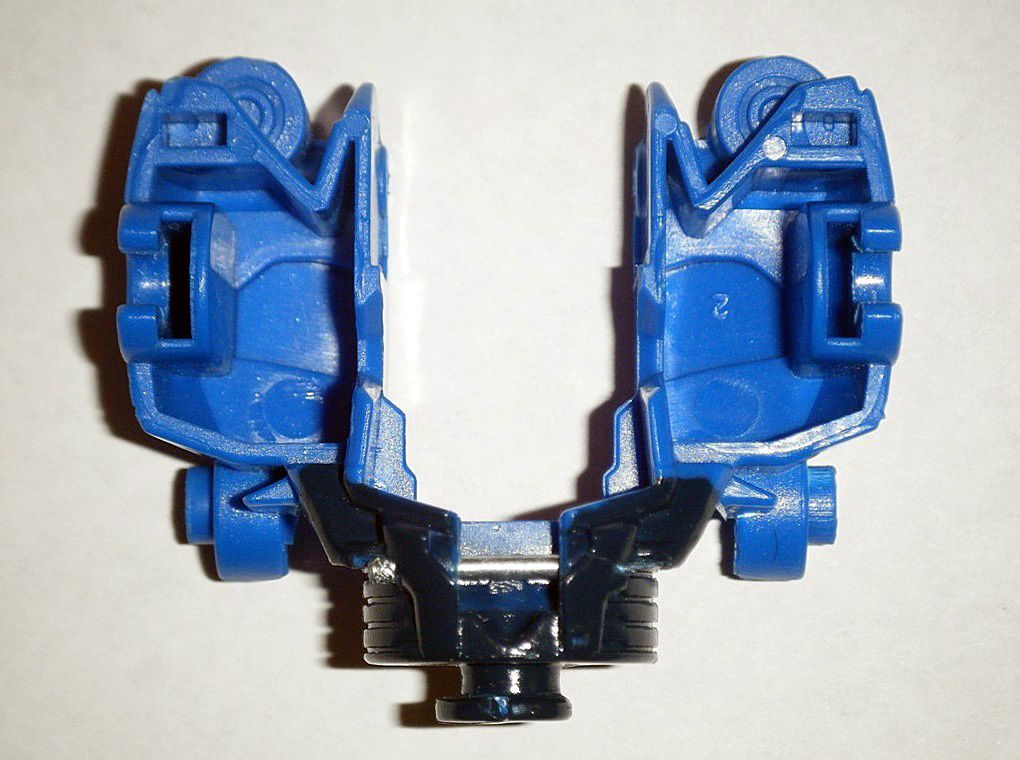
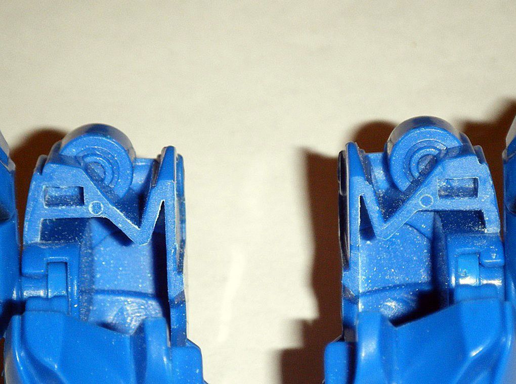
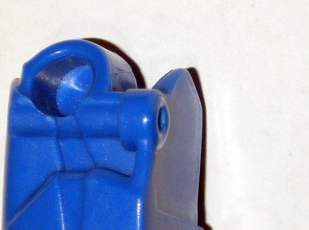
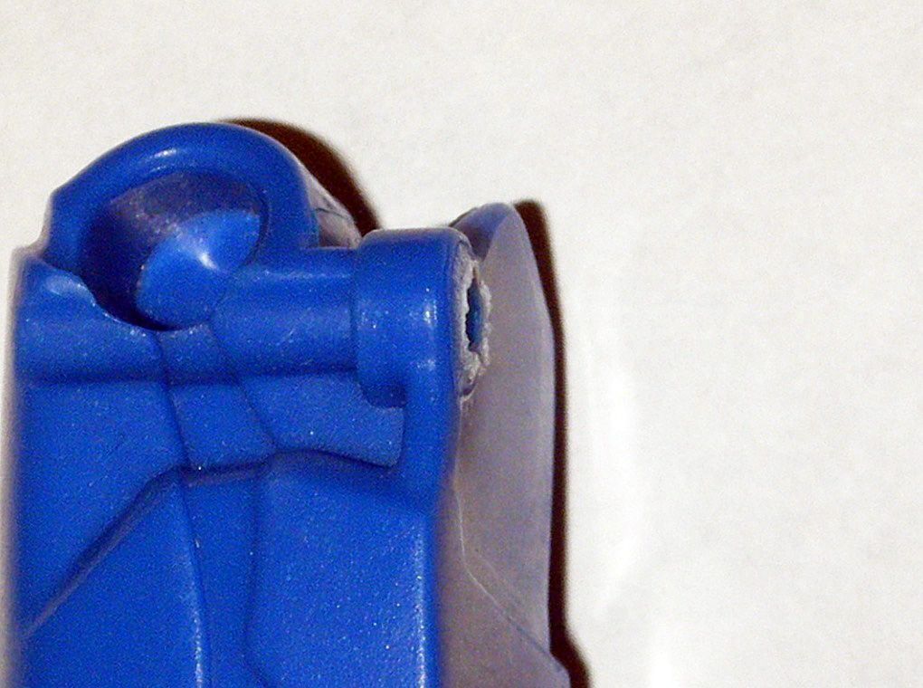
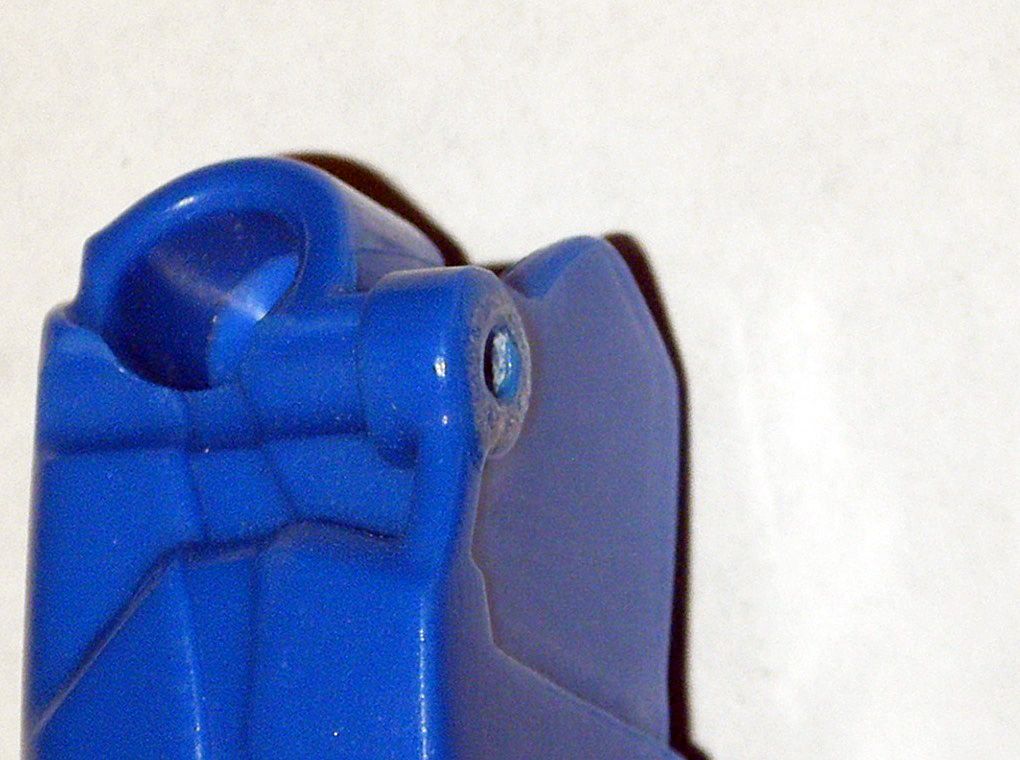
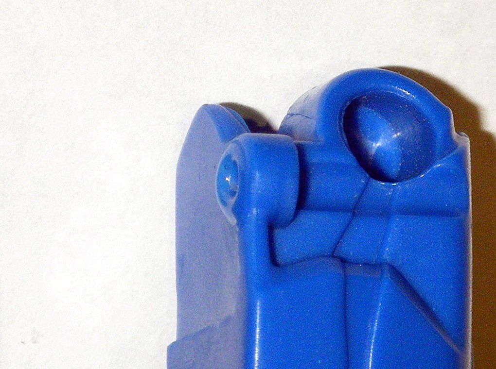
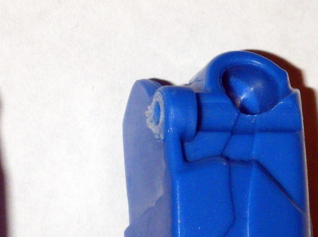
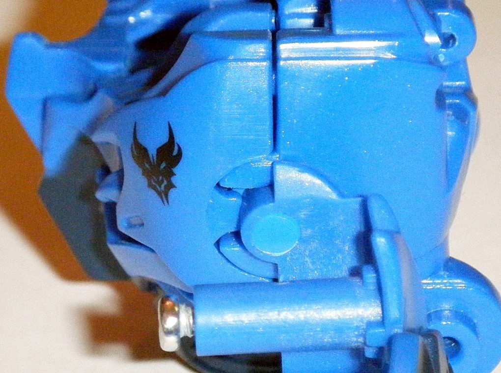
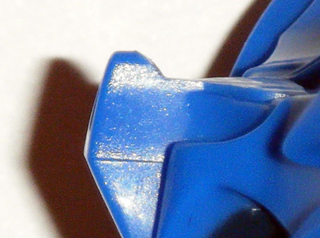
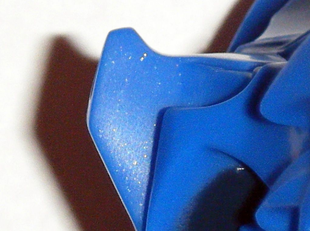
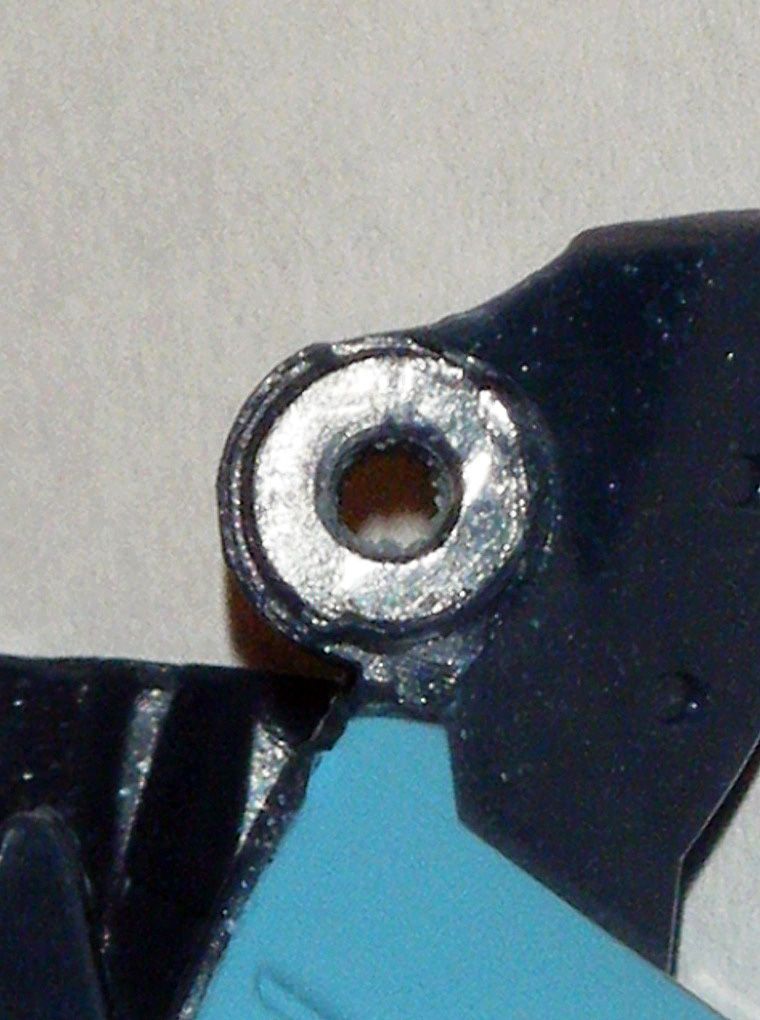
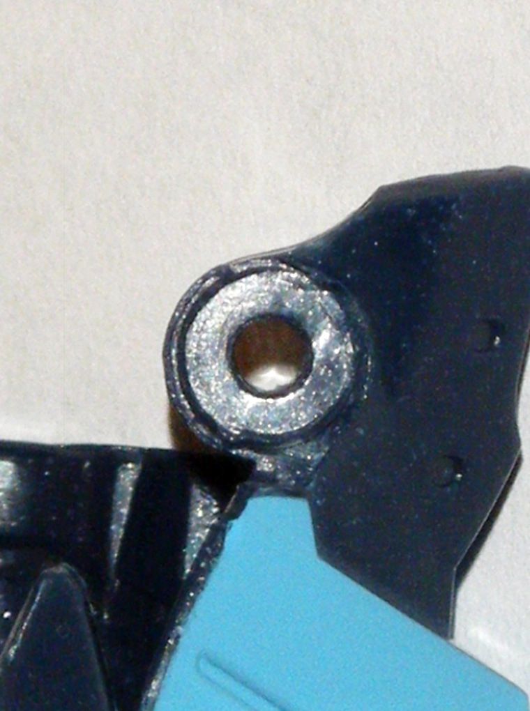
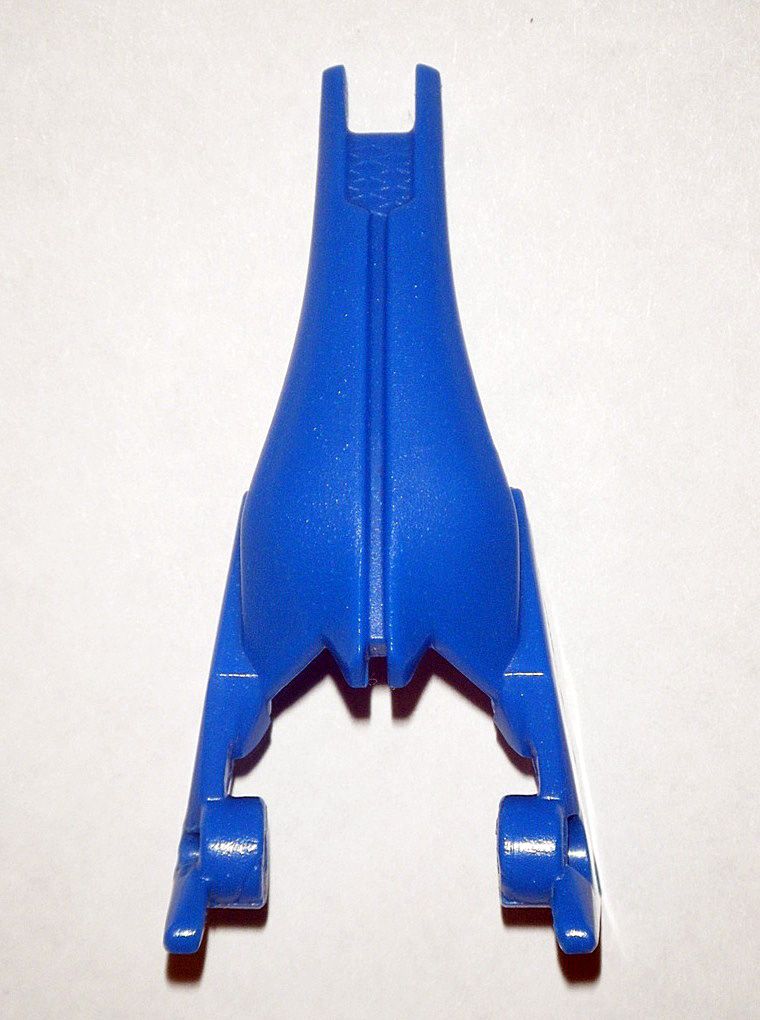
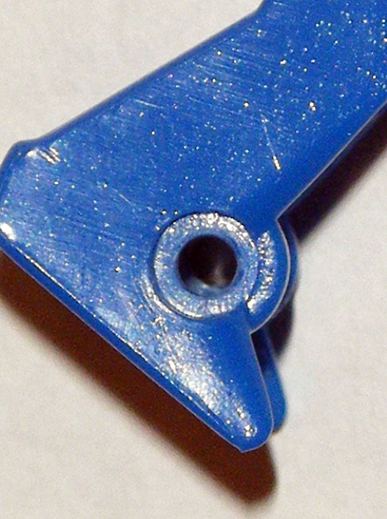
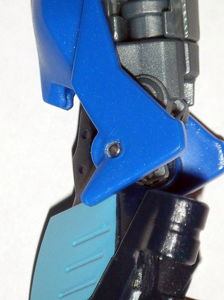
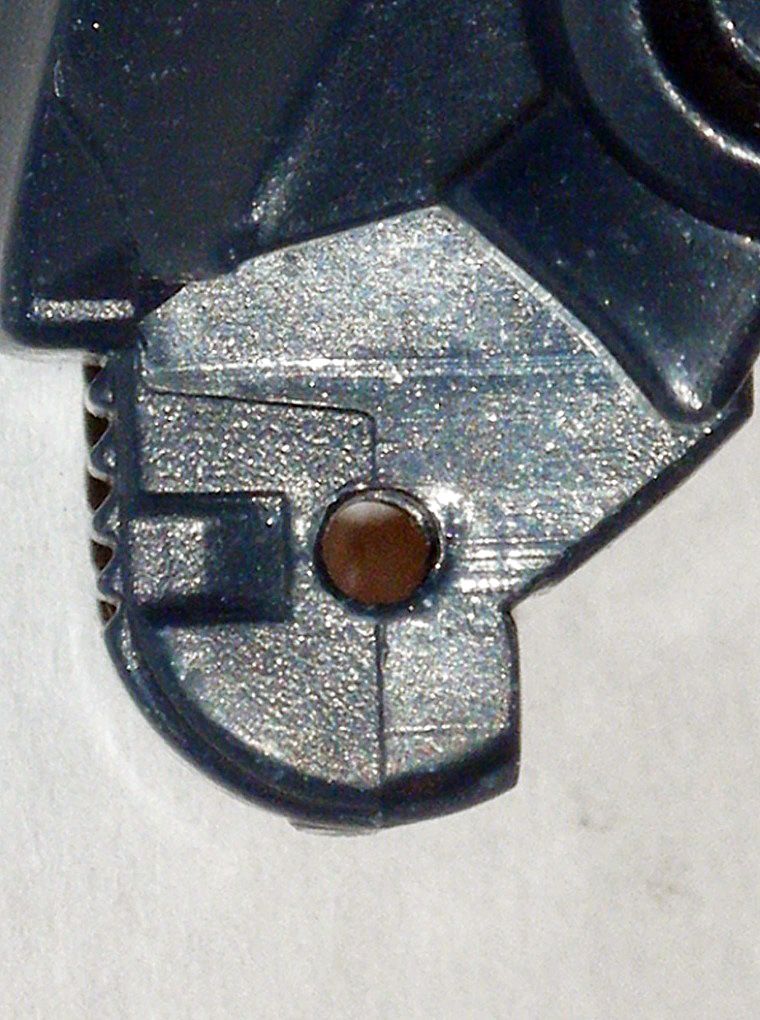
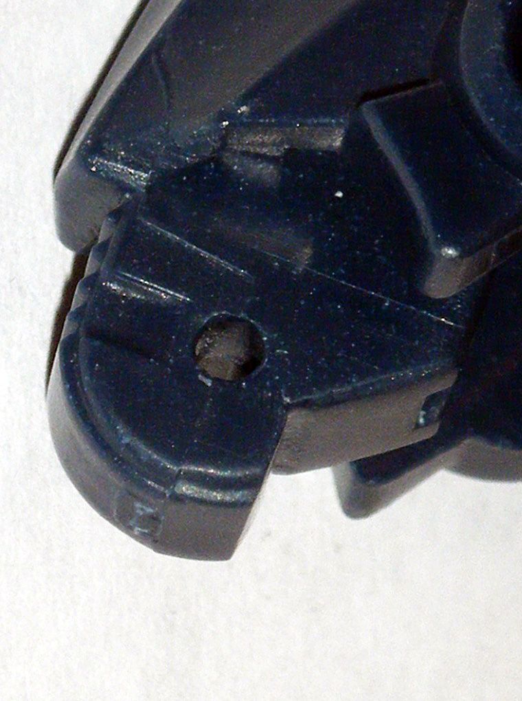
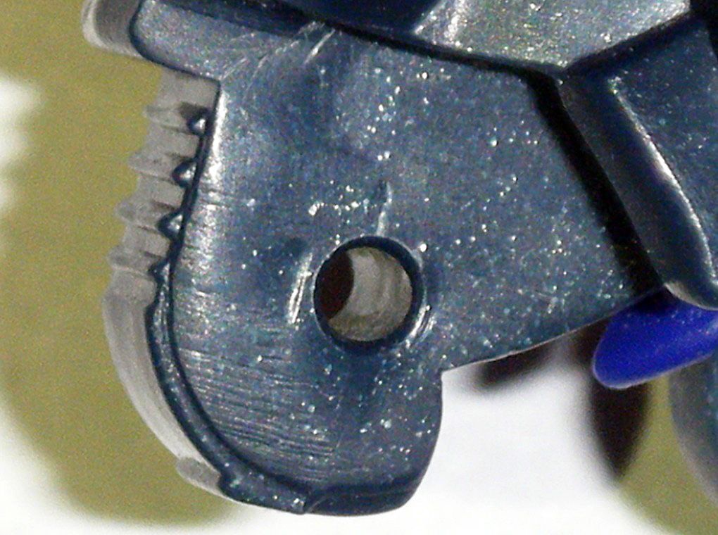
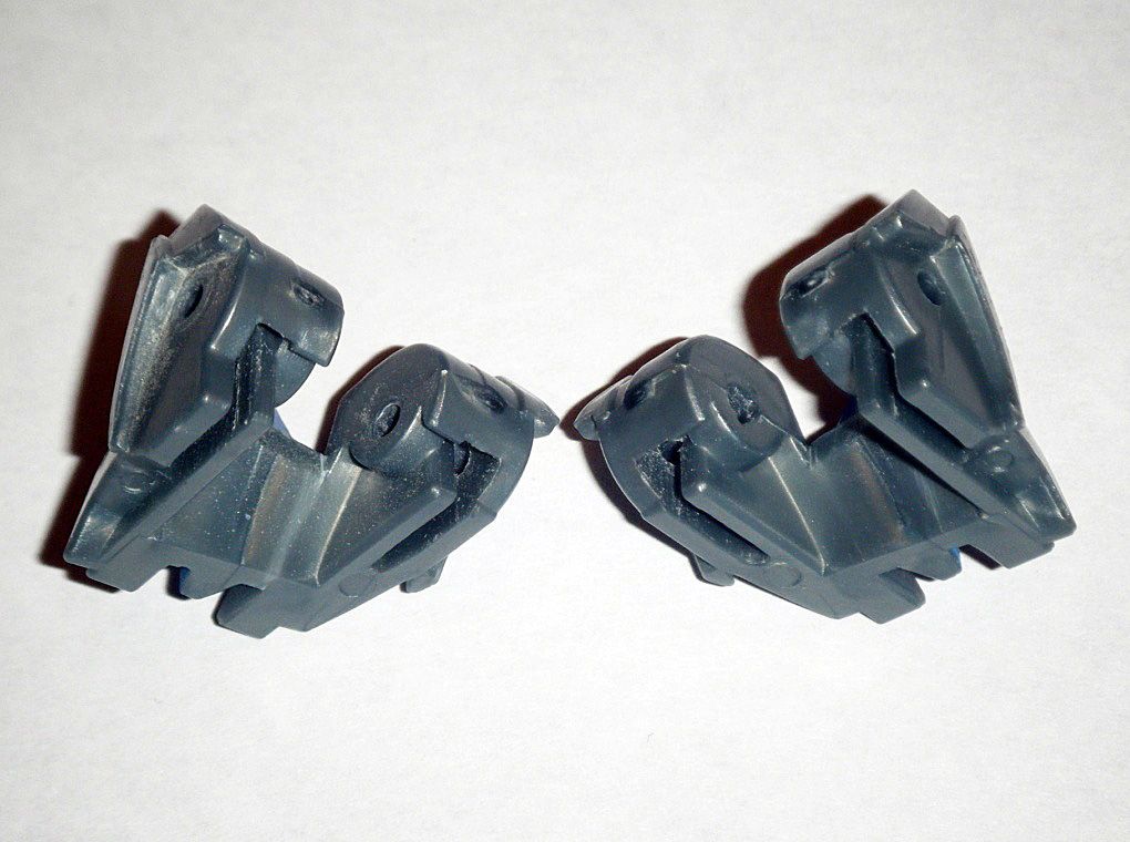
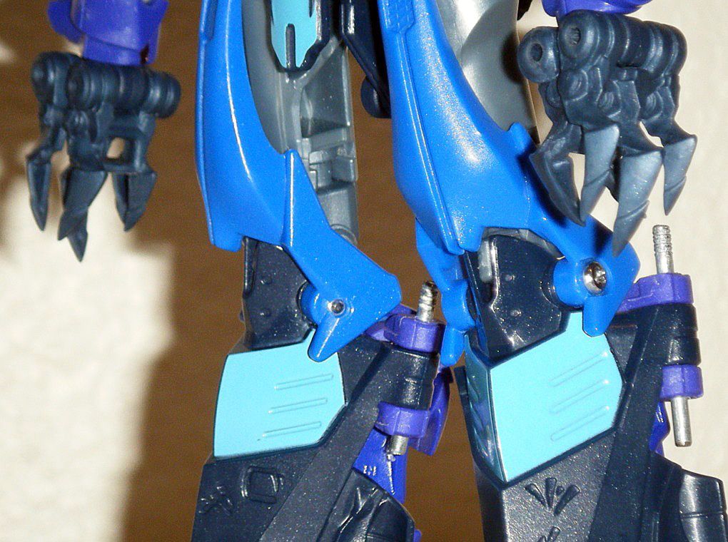
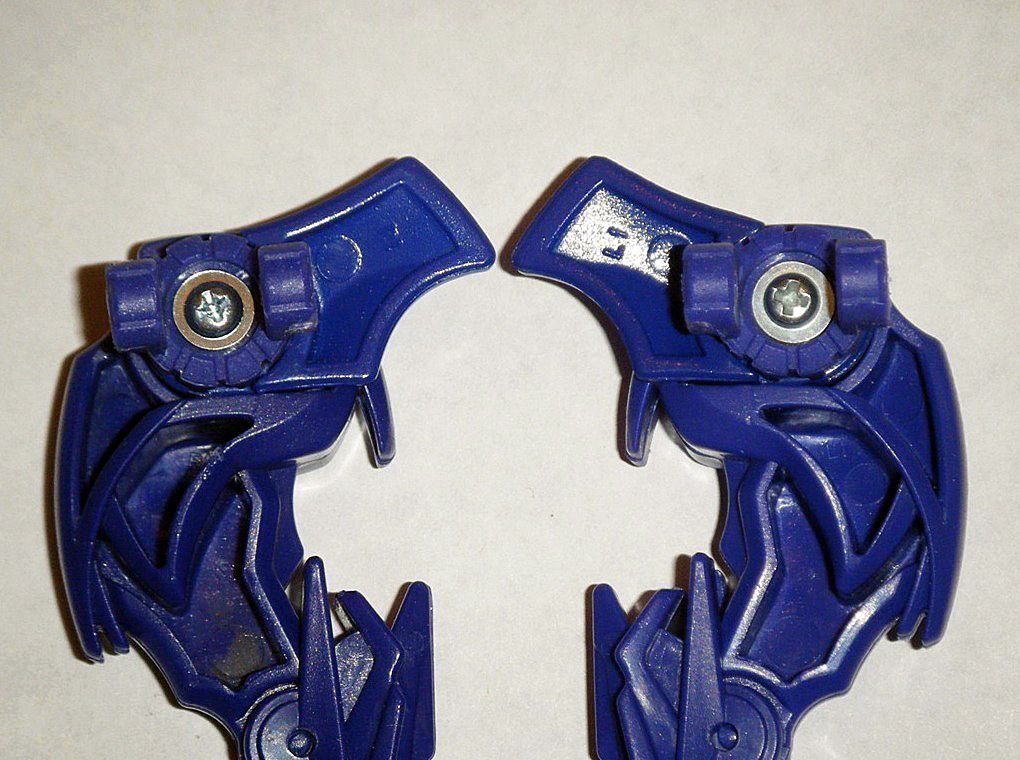
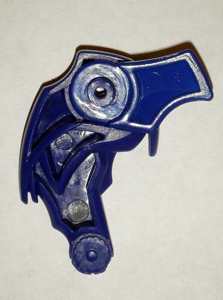
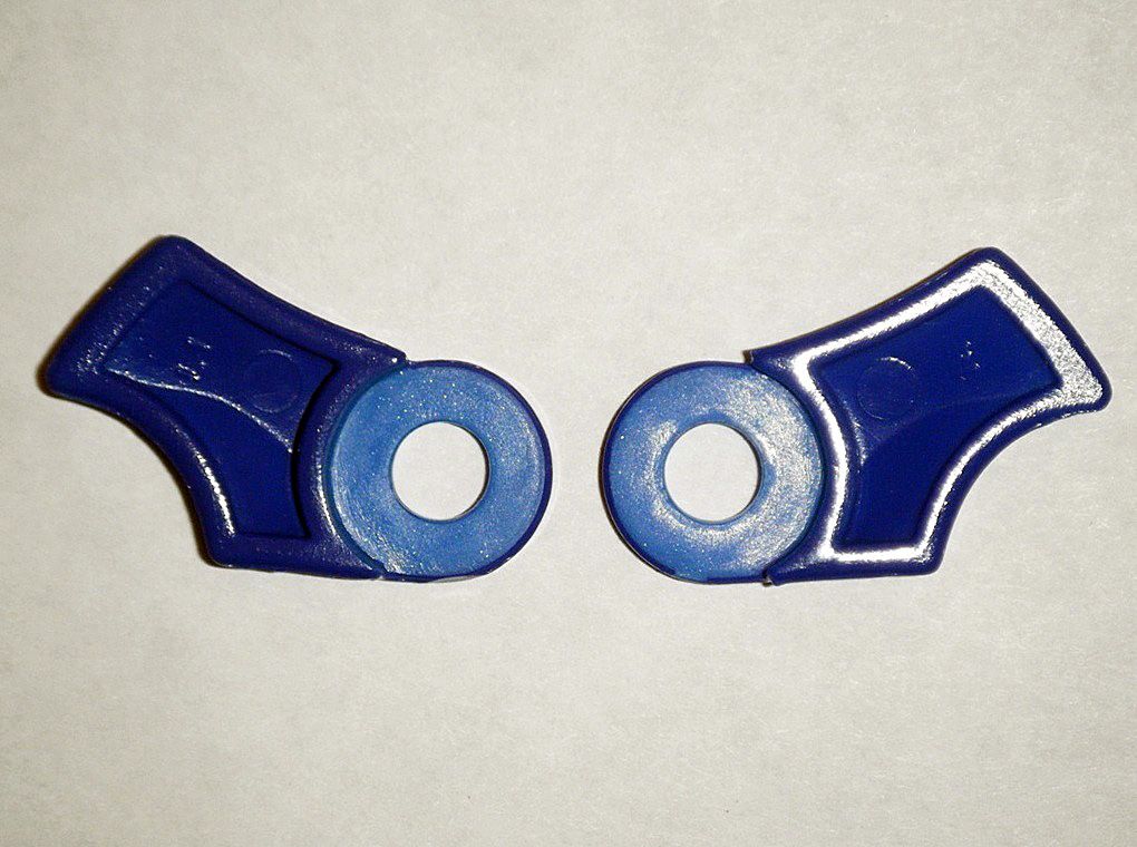
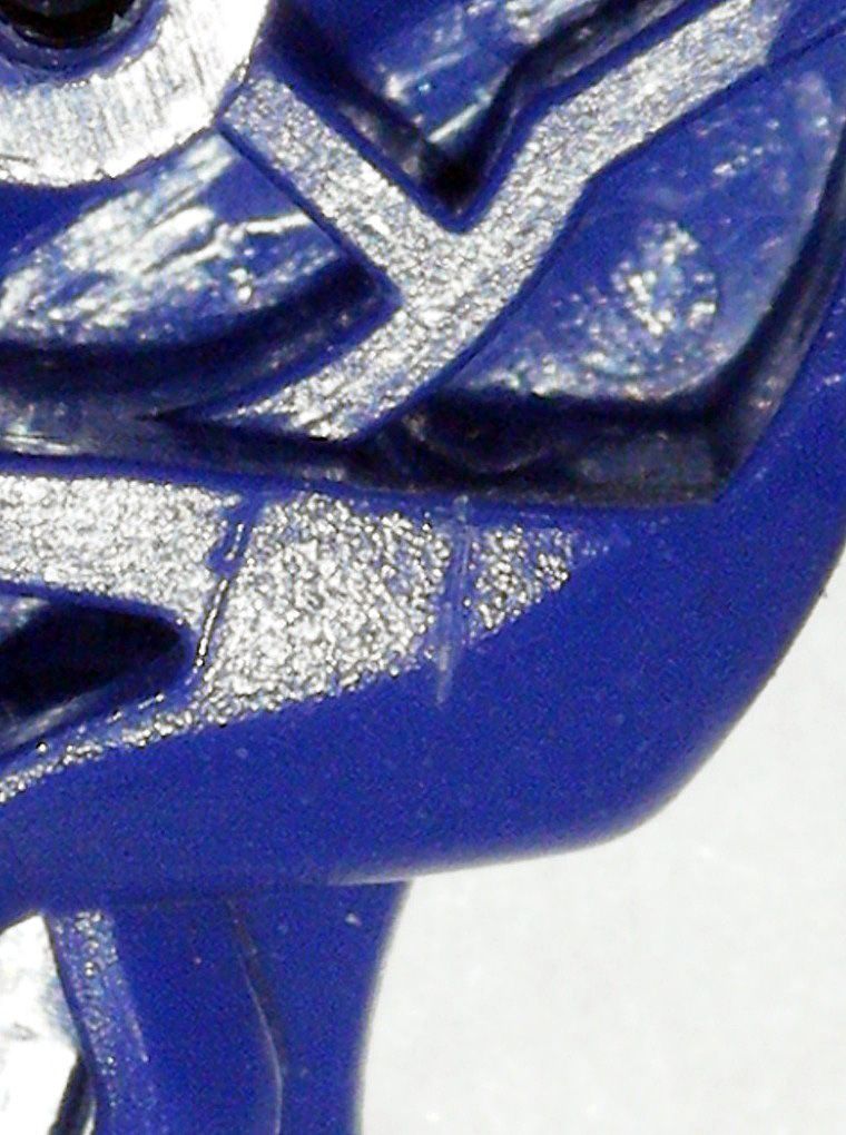
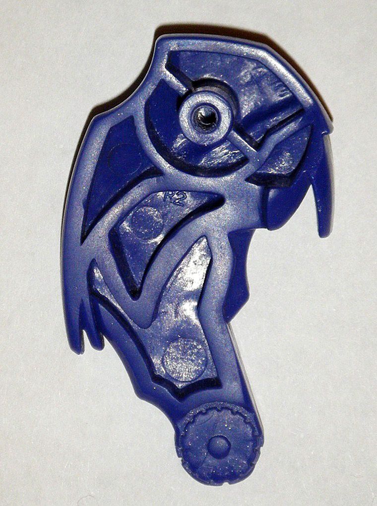
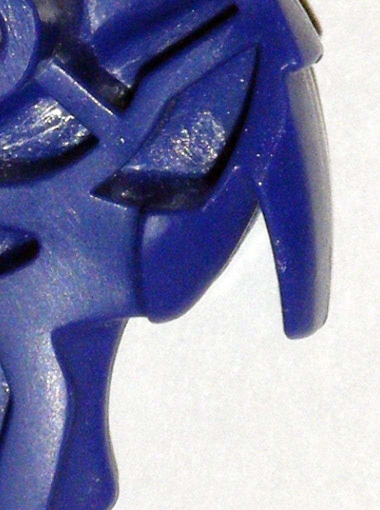
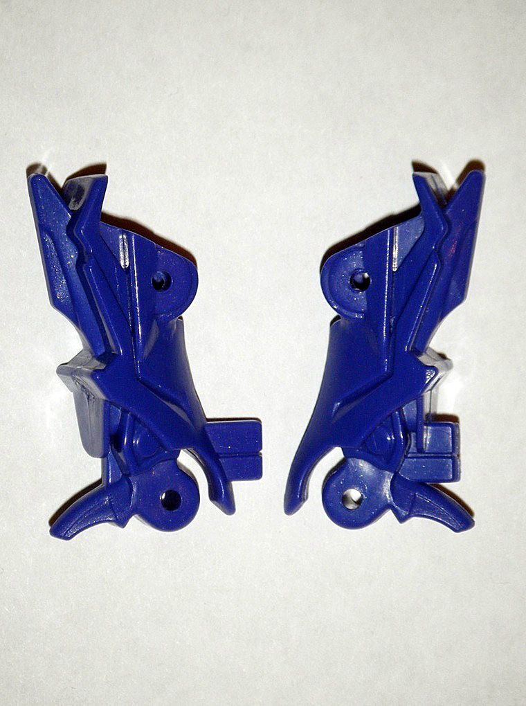
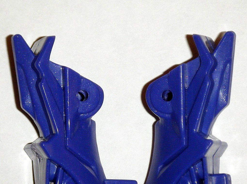
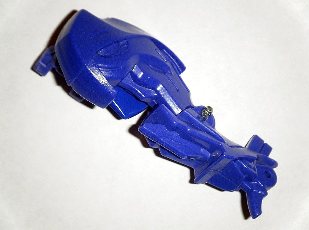
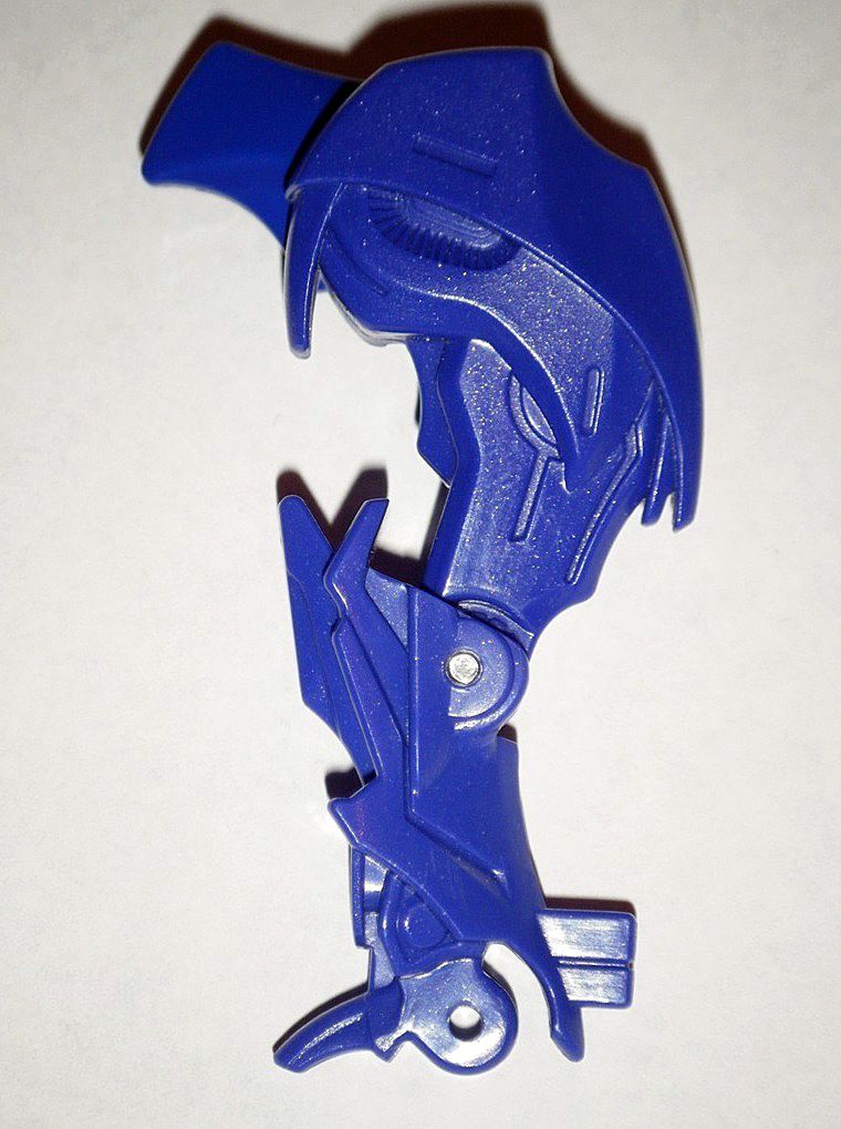
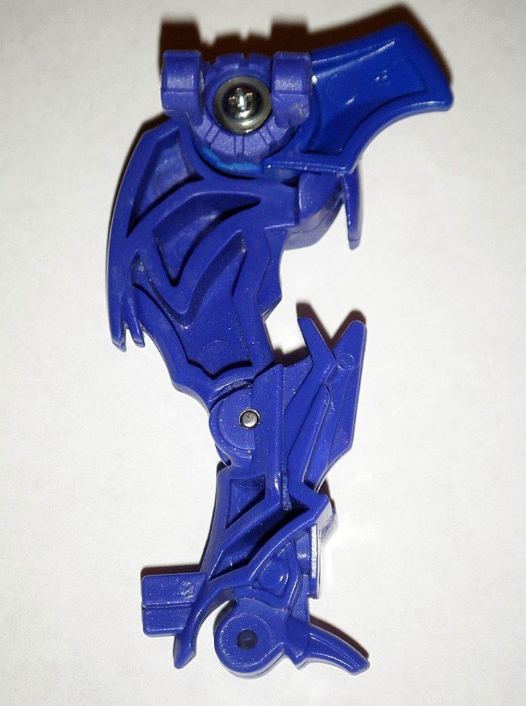
01) Spikes on back of shoulders cut offed and area sanded/polished down:
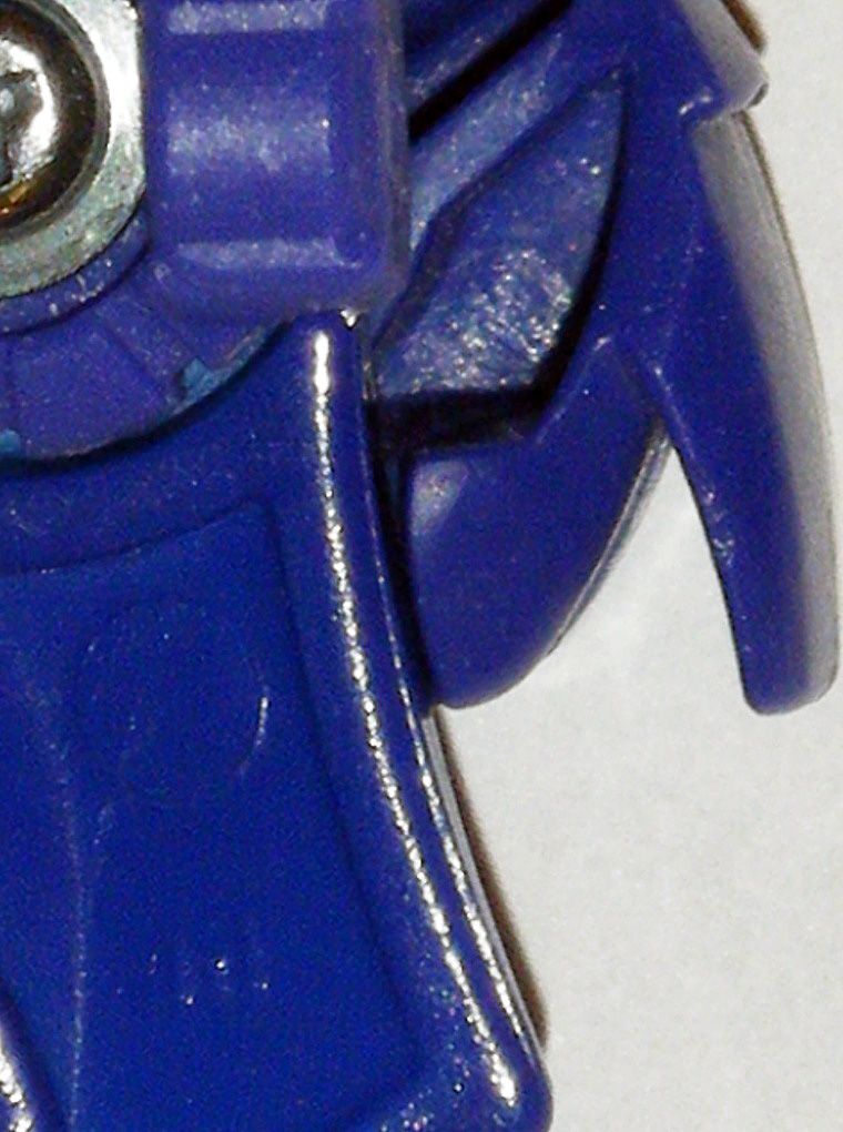
02) Longer folding spikes felt cumbersome to me, so the bars holding them were removed and outer ends cut/sanded/polished into a curved spike:
03) Front and middle spikes reshaped into points:
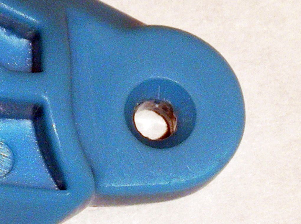
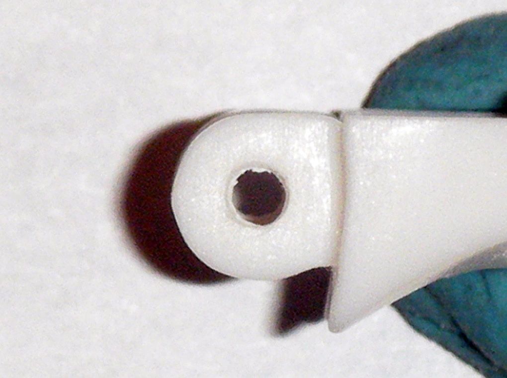
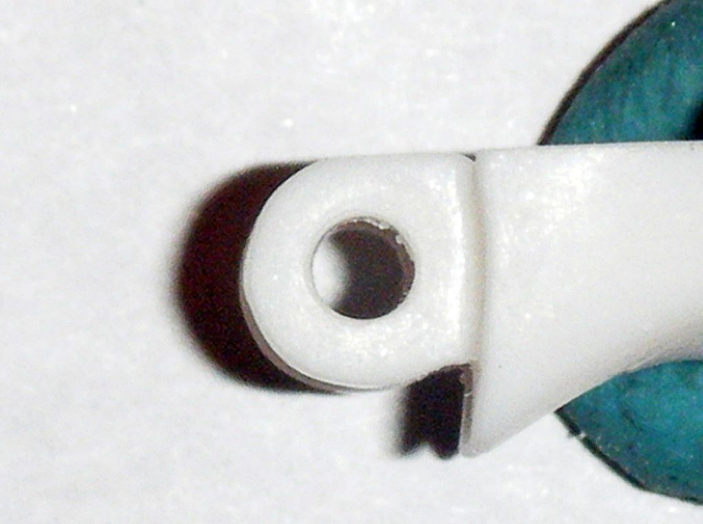
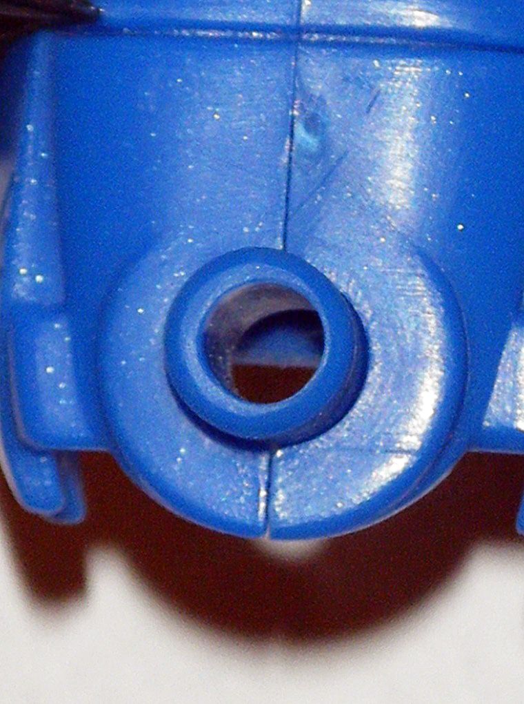
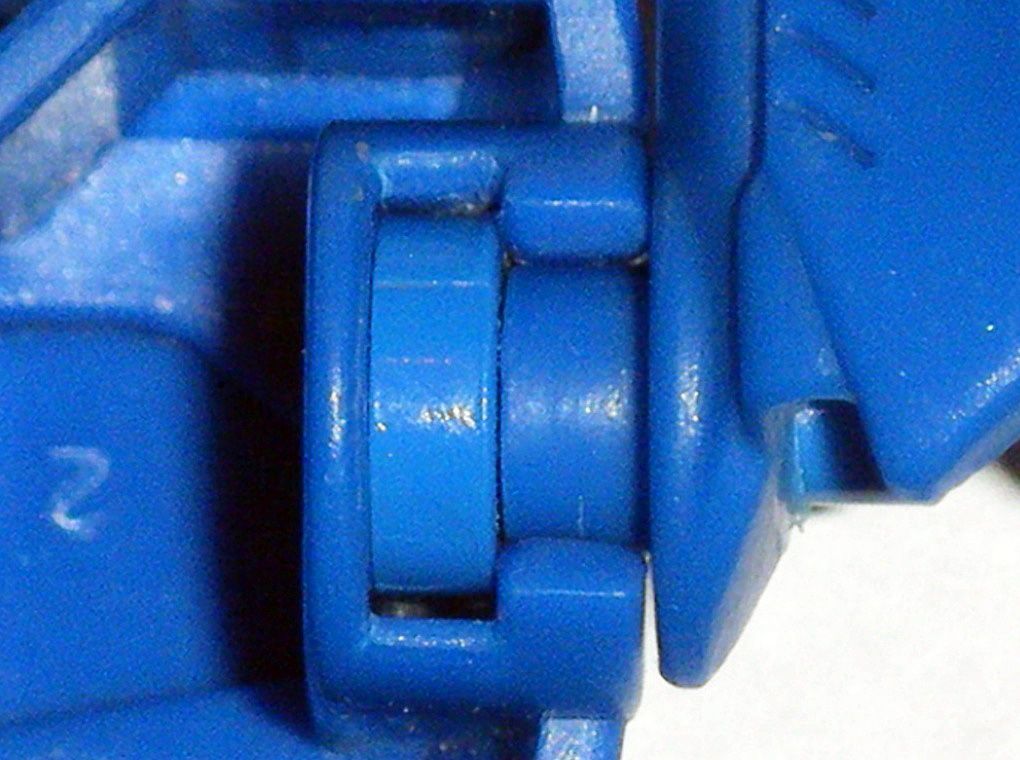
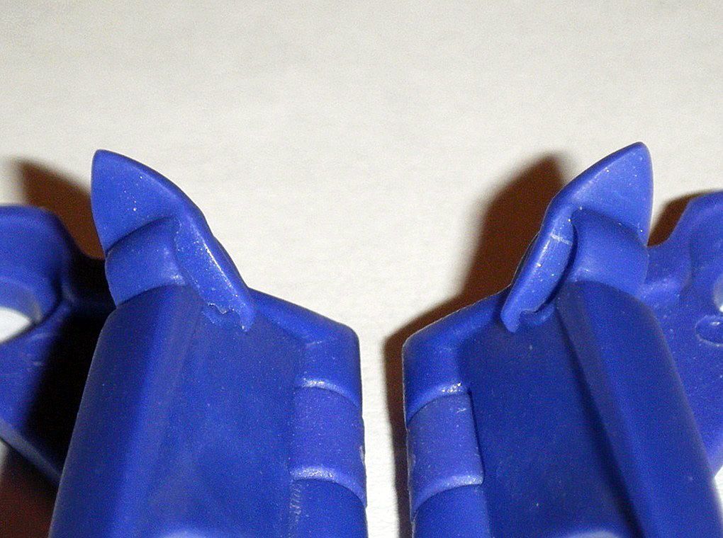
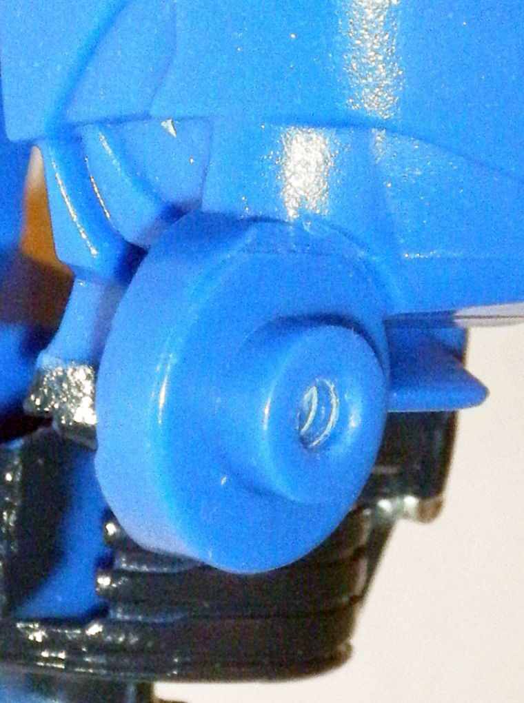
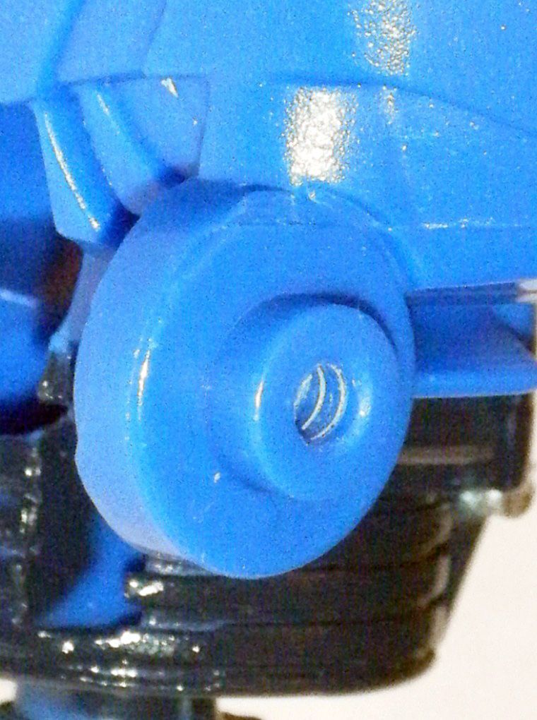
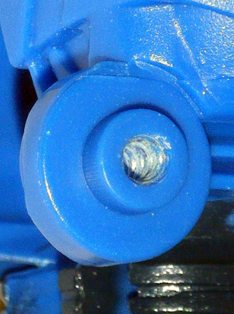
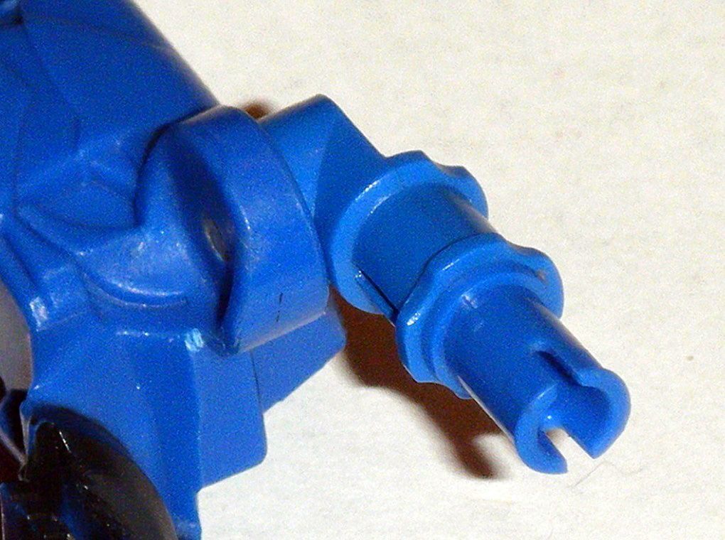
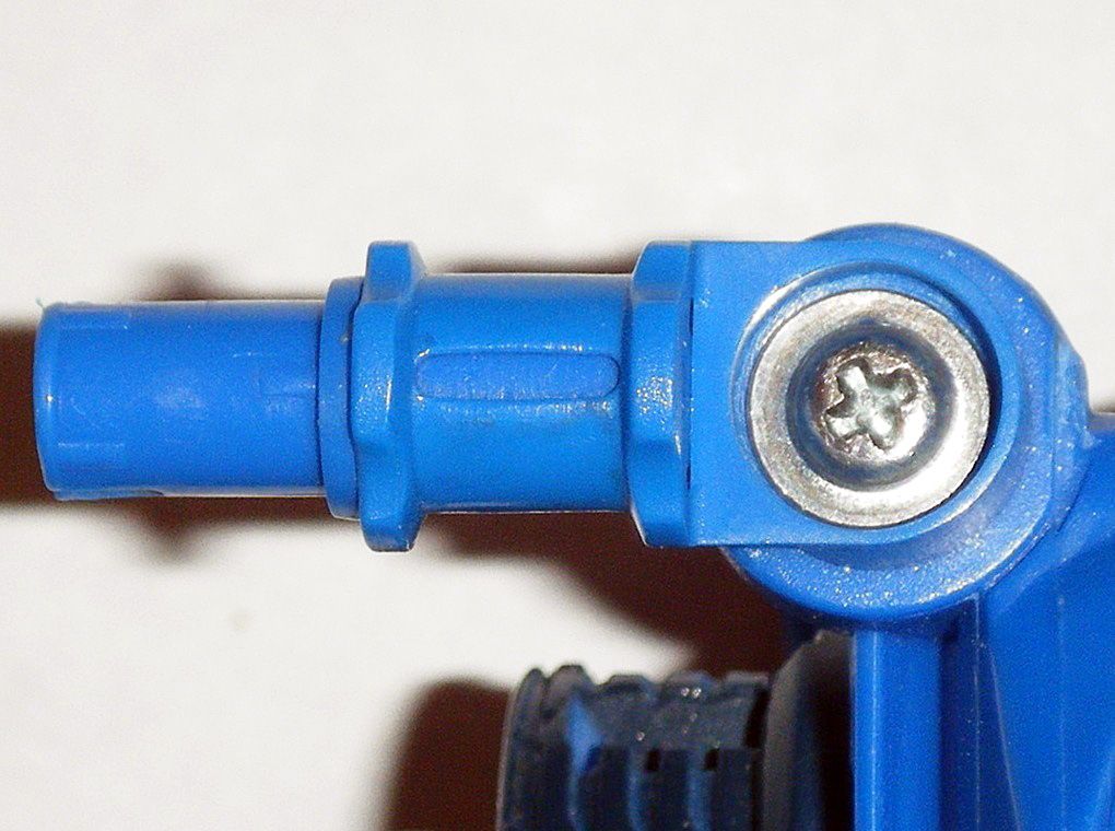
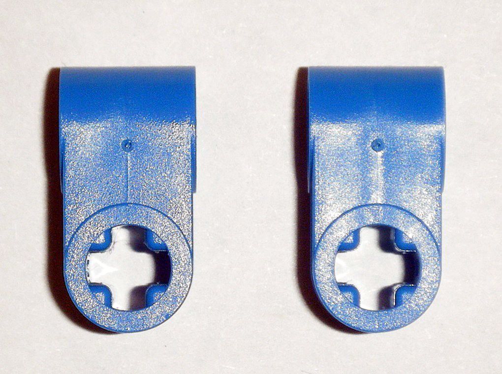
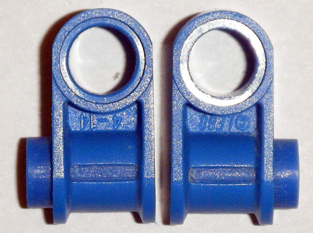
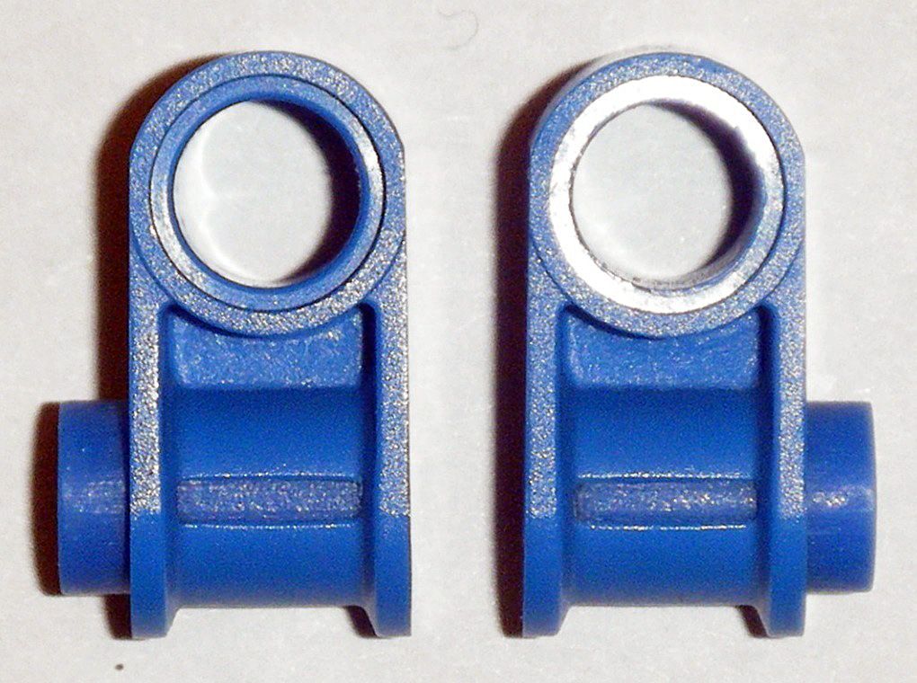
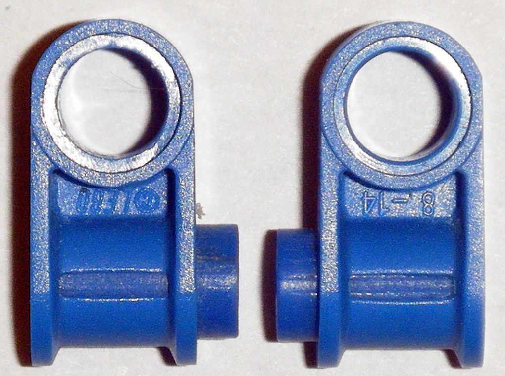
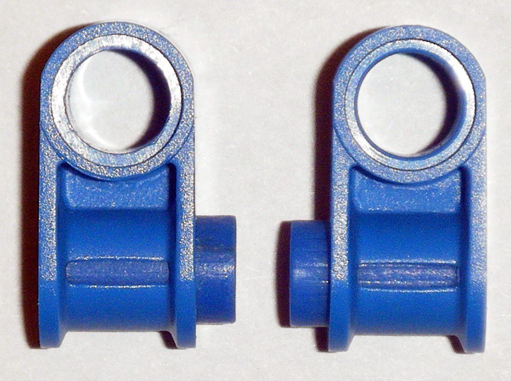
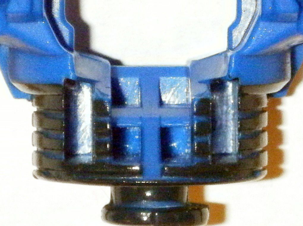
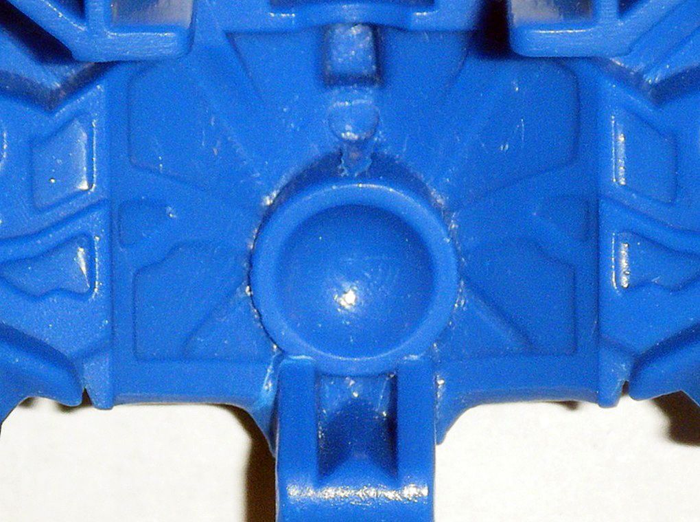
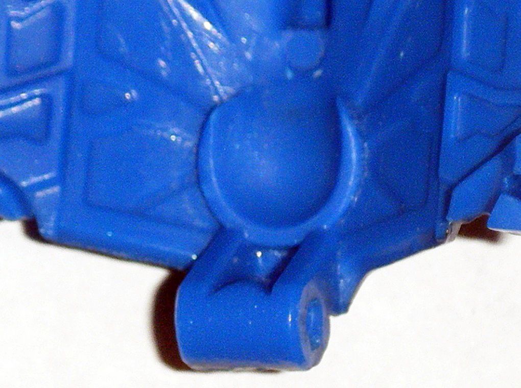
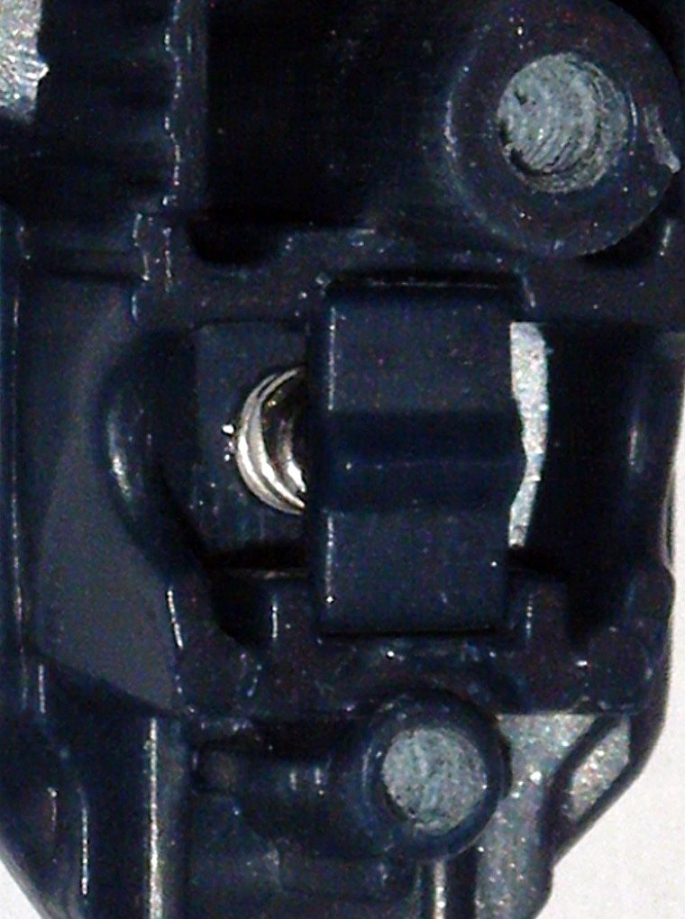
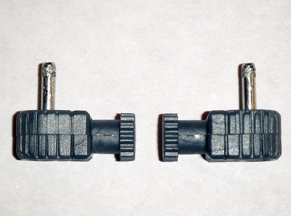
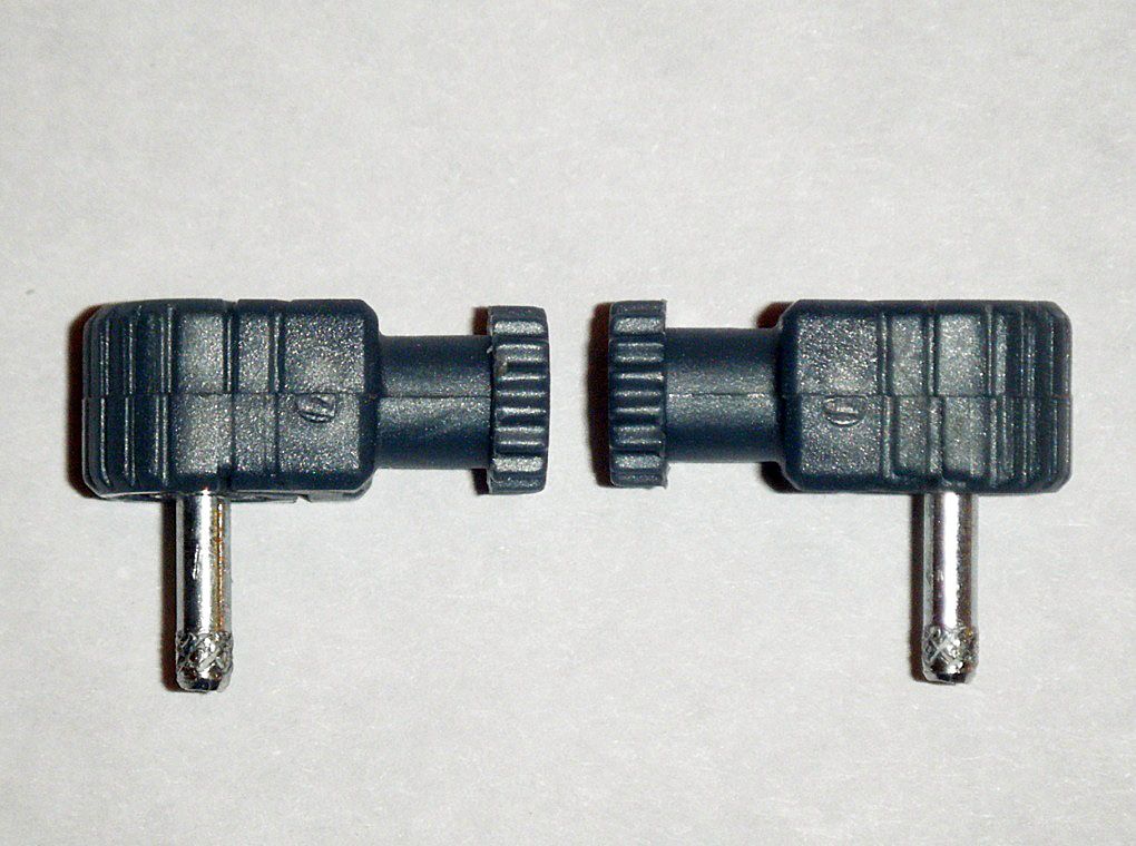
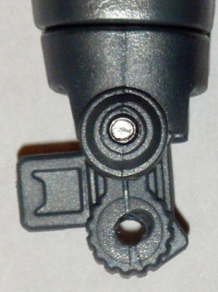
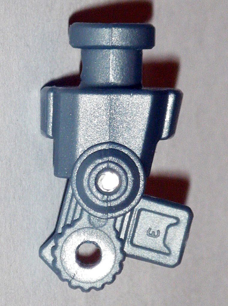
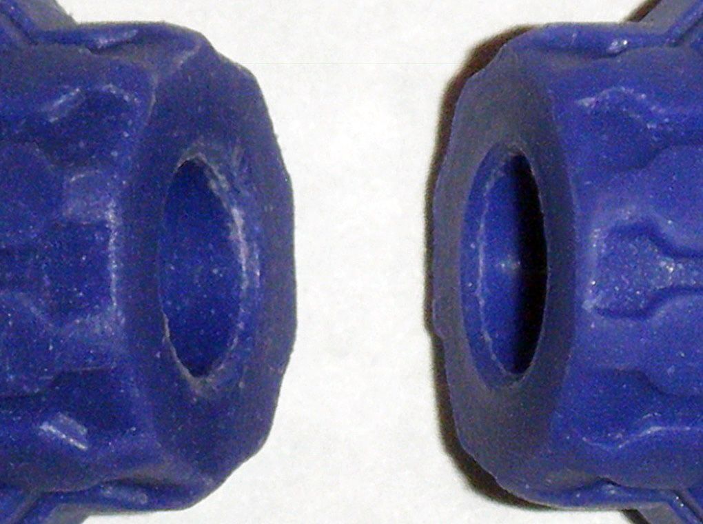
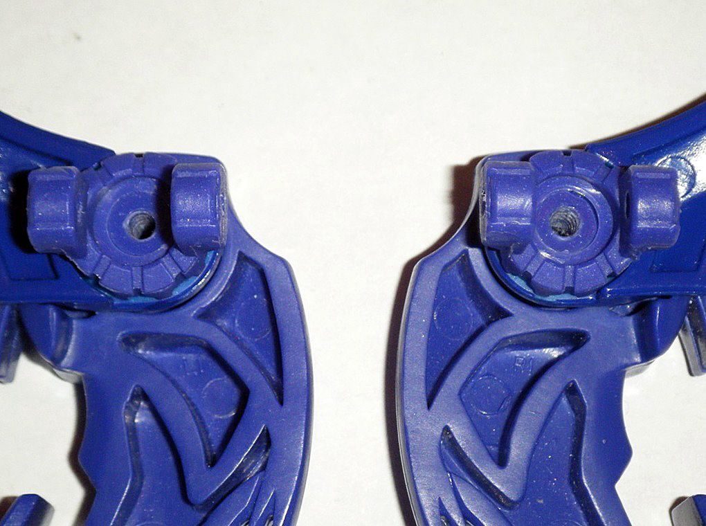
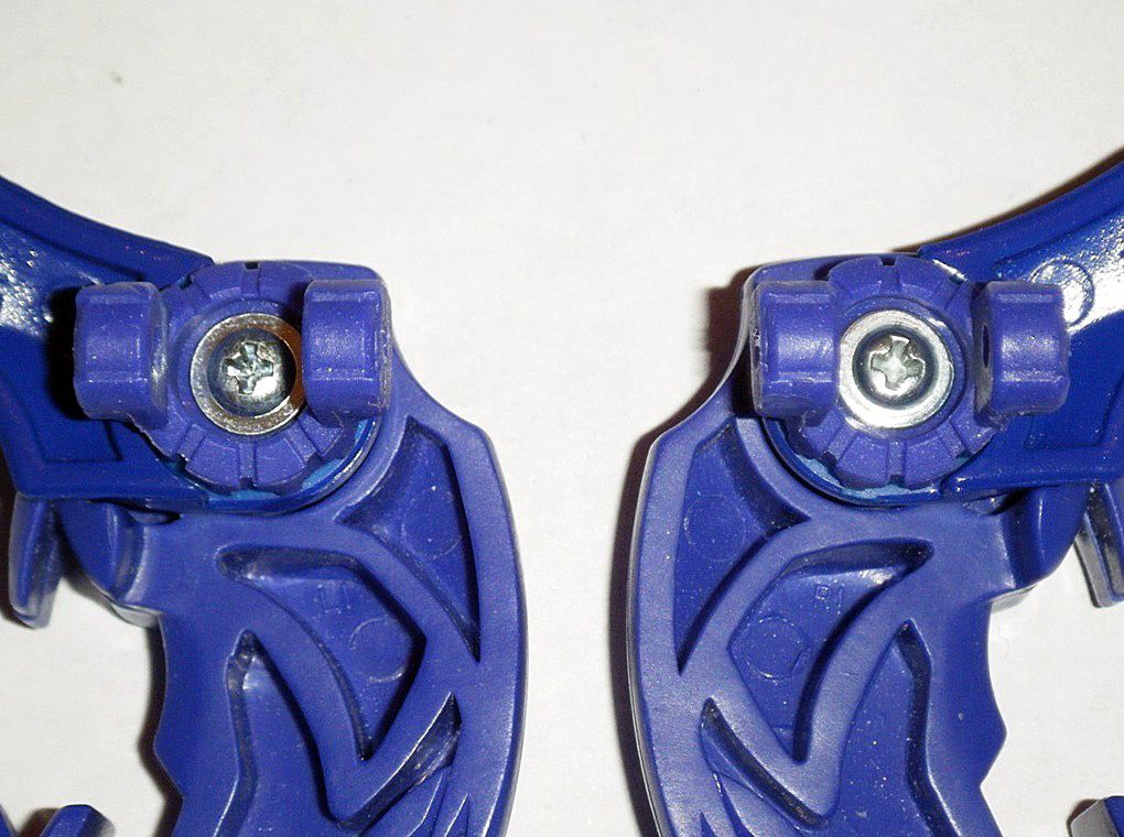
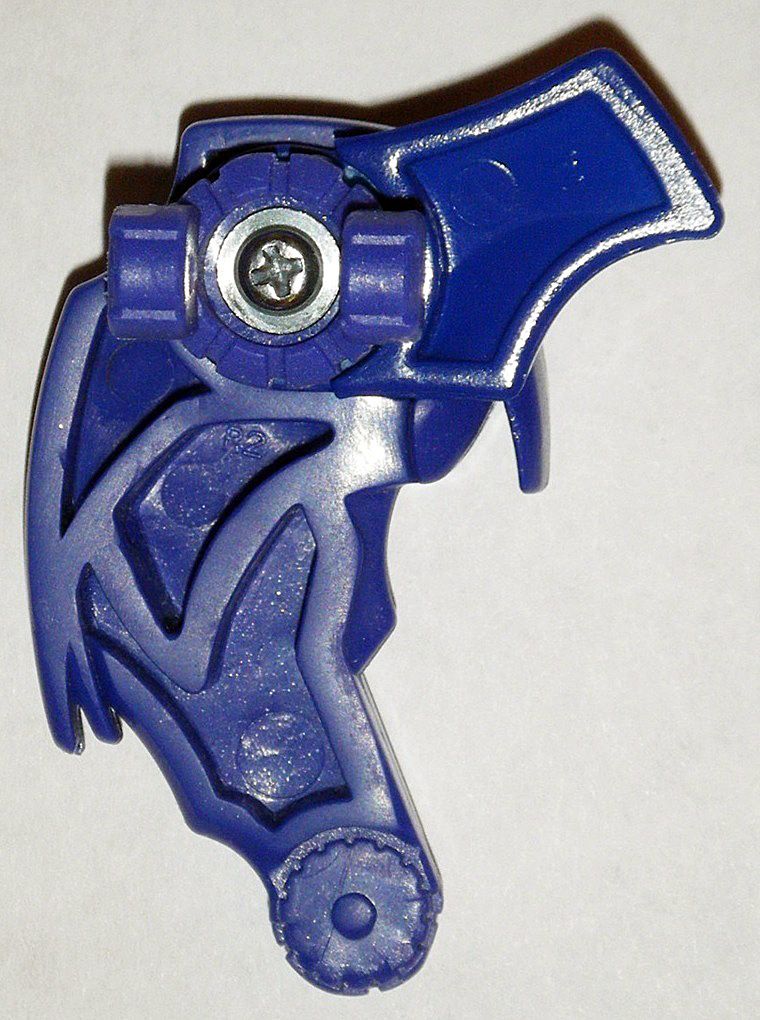
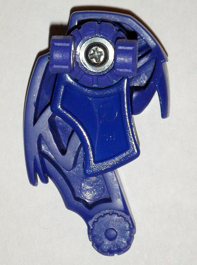
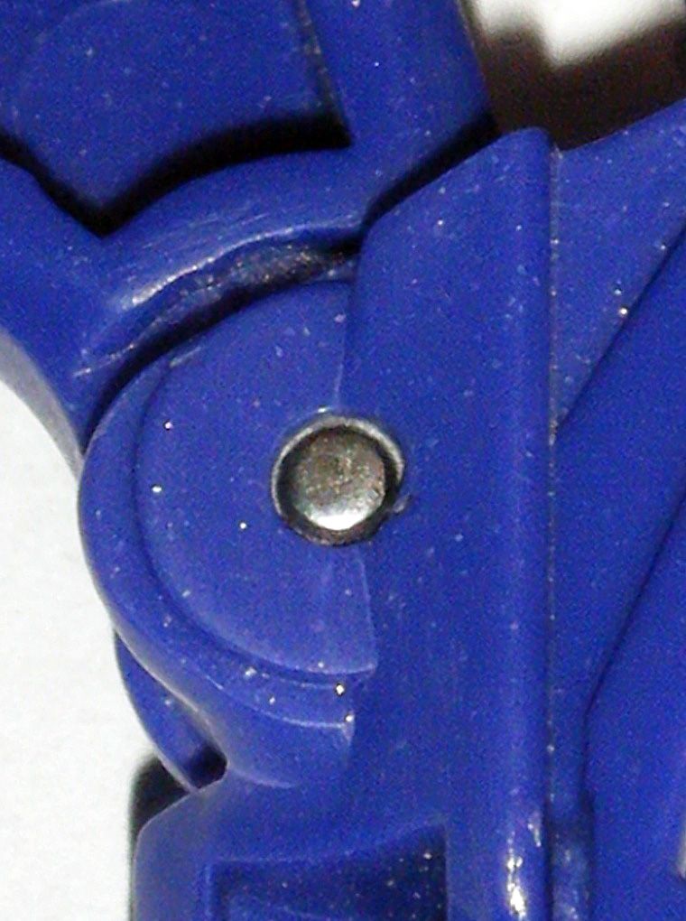
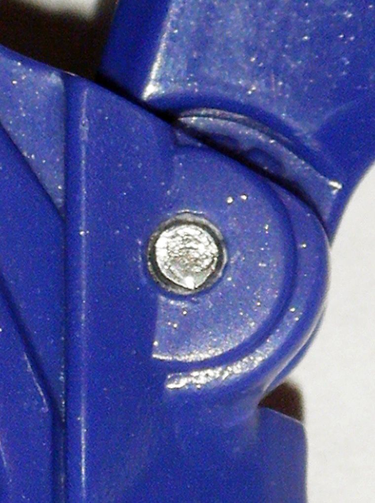
04) Shoulder joints felt to loose for me. Needed to modify and remake them:
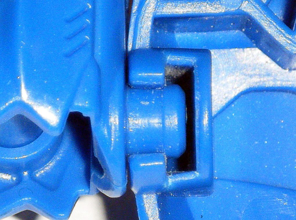
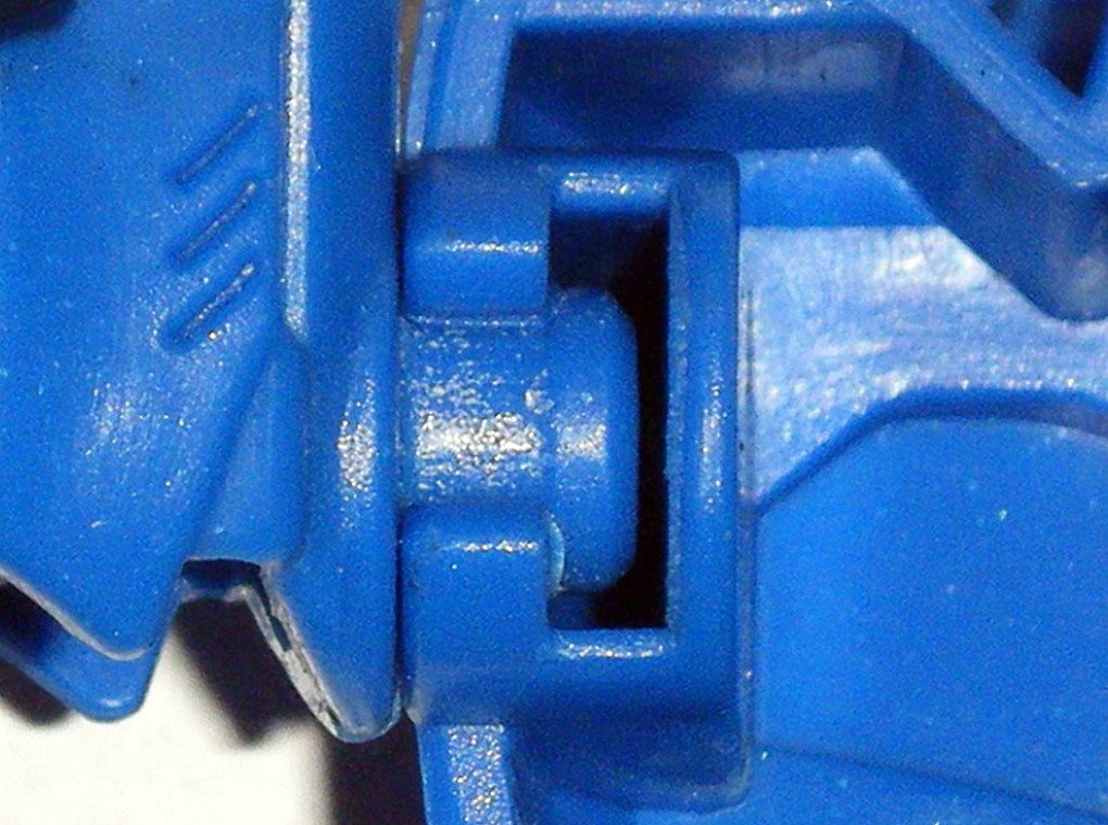
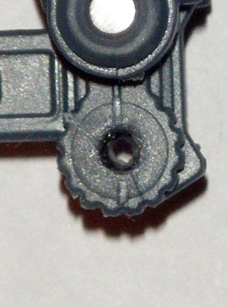
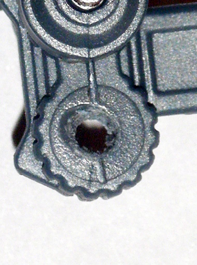
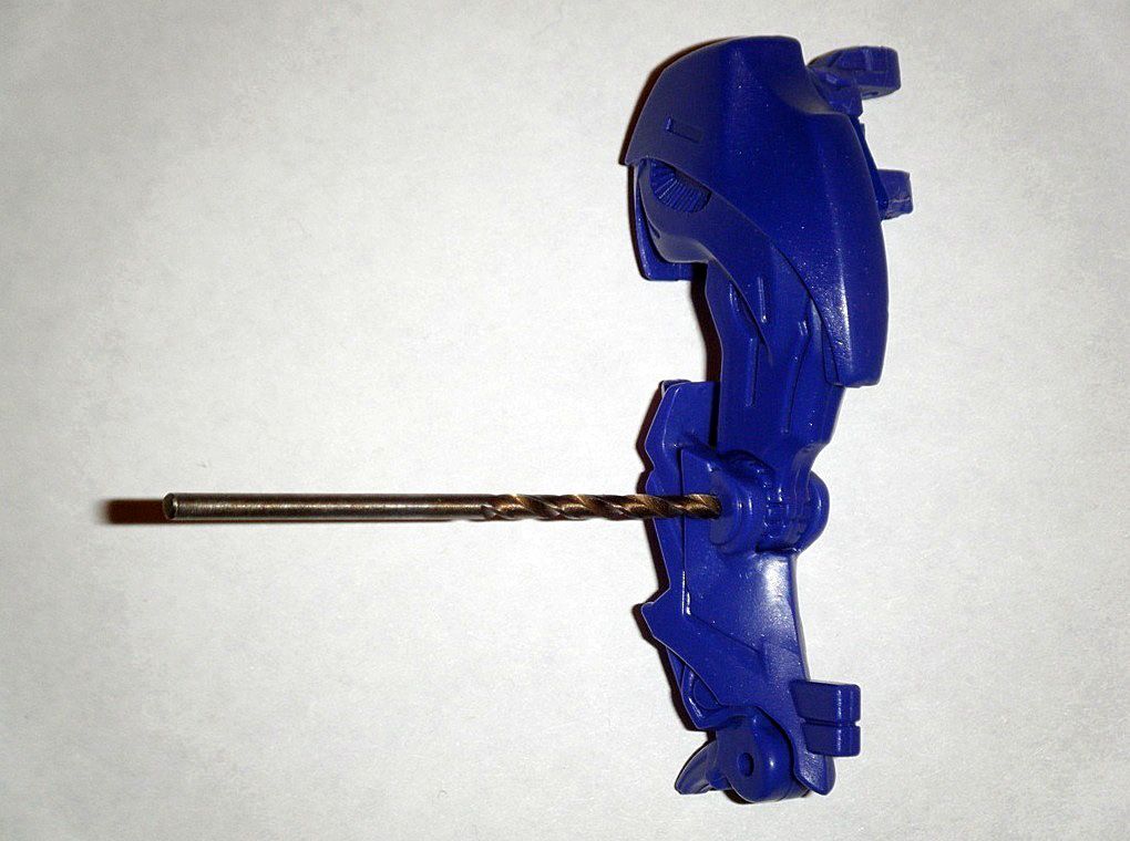
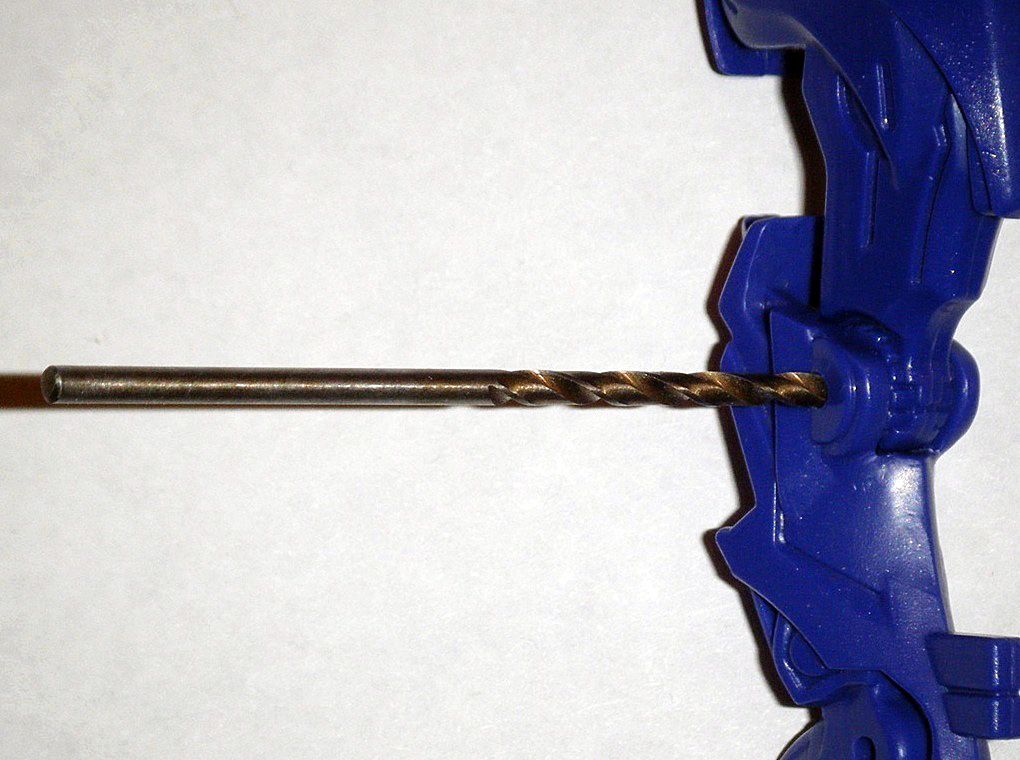
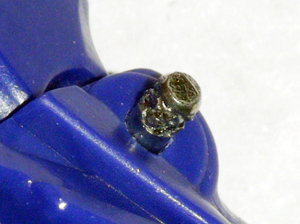
05) Carefully sanded/polished down opening of joint socket for easy removal of shoulder without suffering any damage:
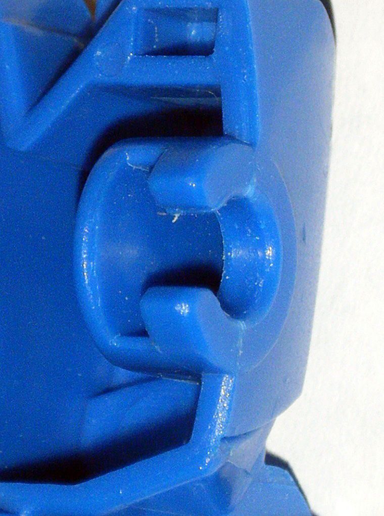
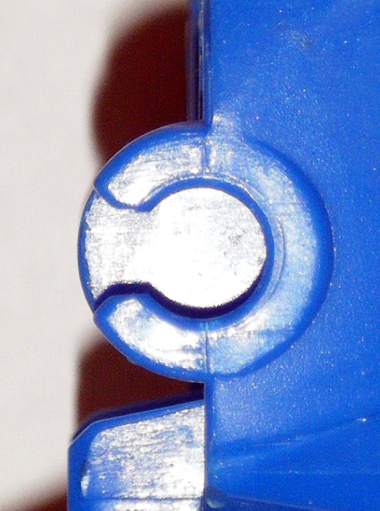
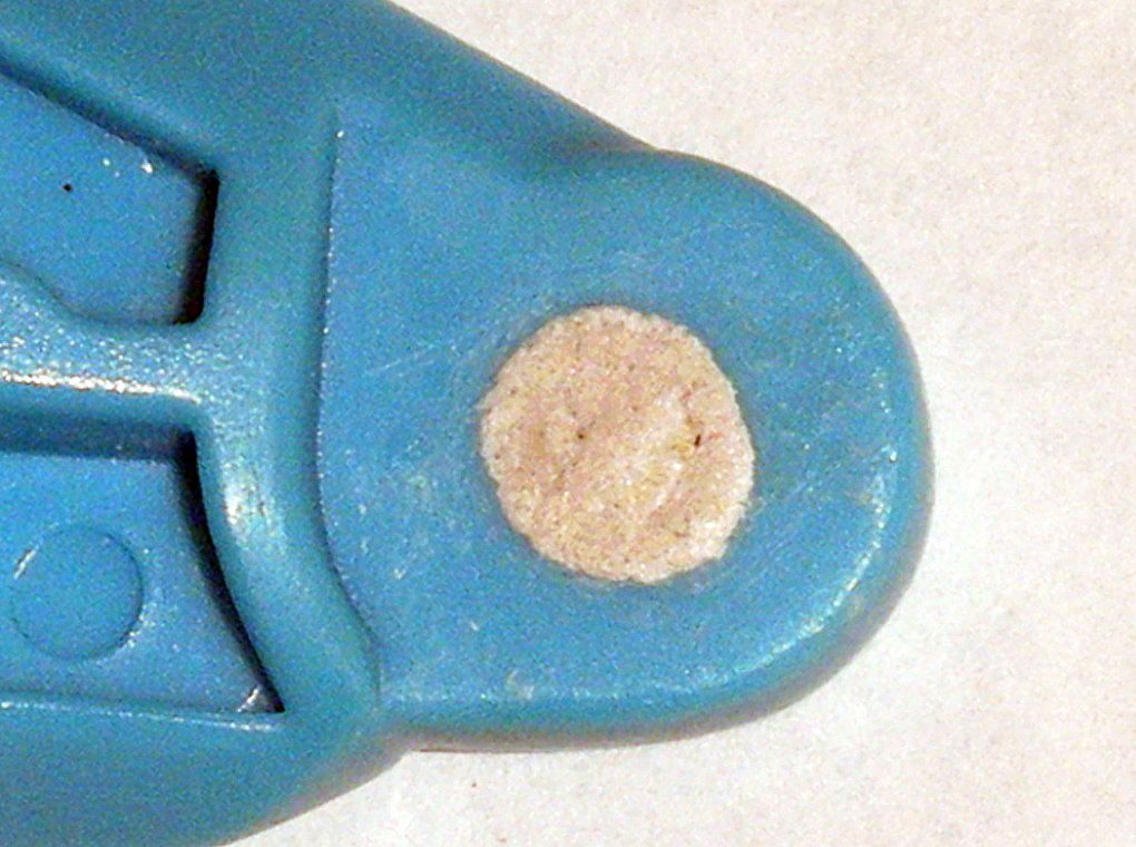
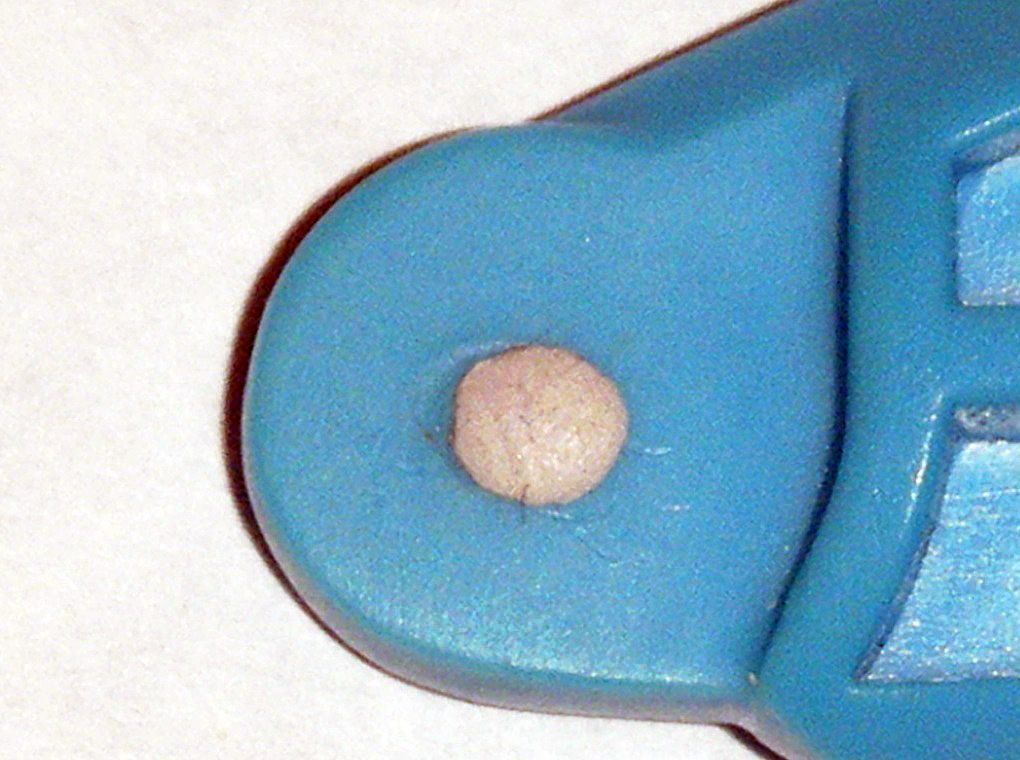
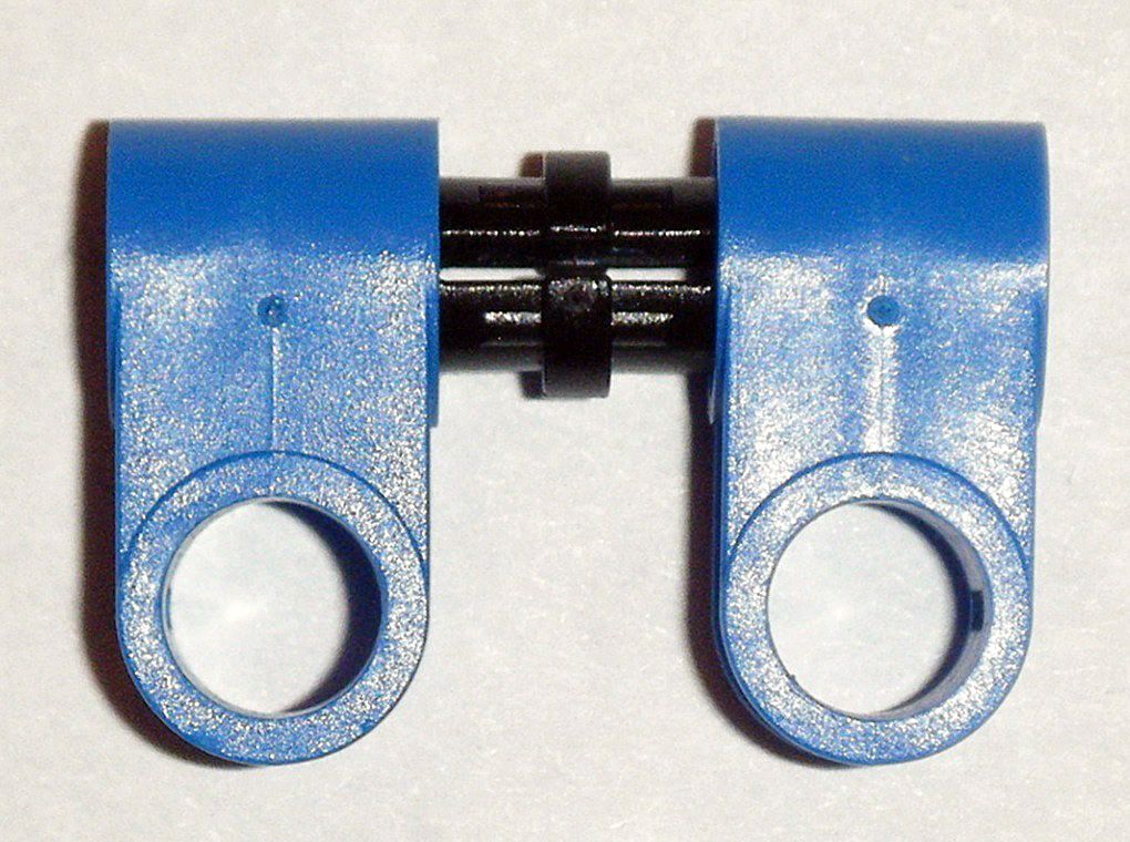
06) Used spike to apply a small hole on center of joint peg in order to carefully drill hole through at low speed using, in order
Dremel 1/32”,
3/64”,
1/16” drill bits,
ACE 5/64” drill bit:
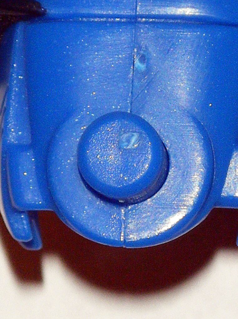
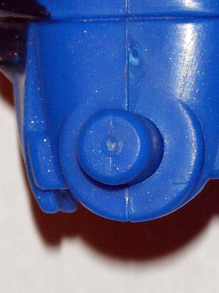
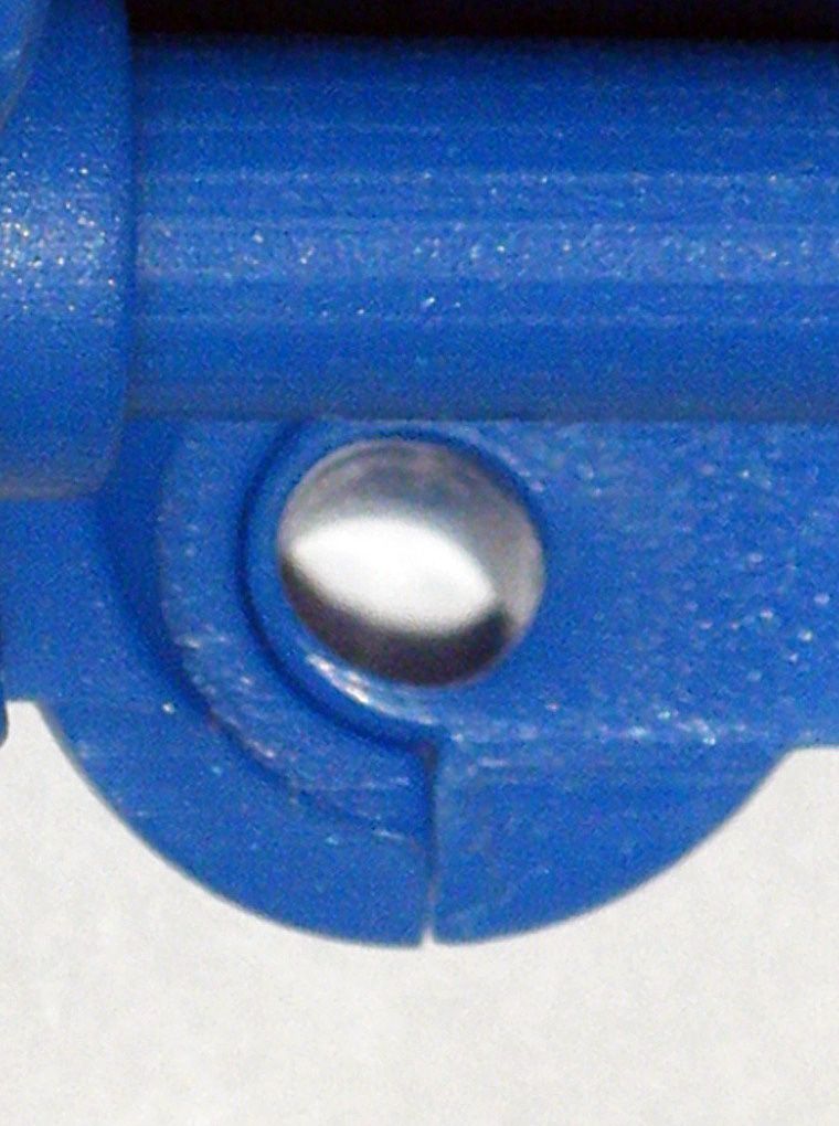
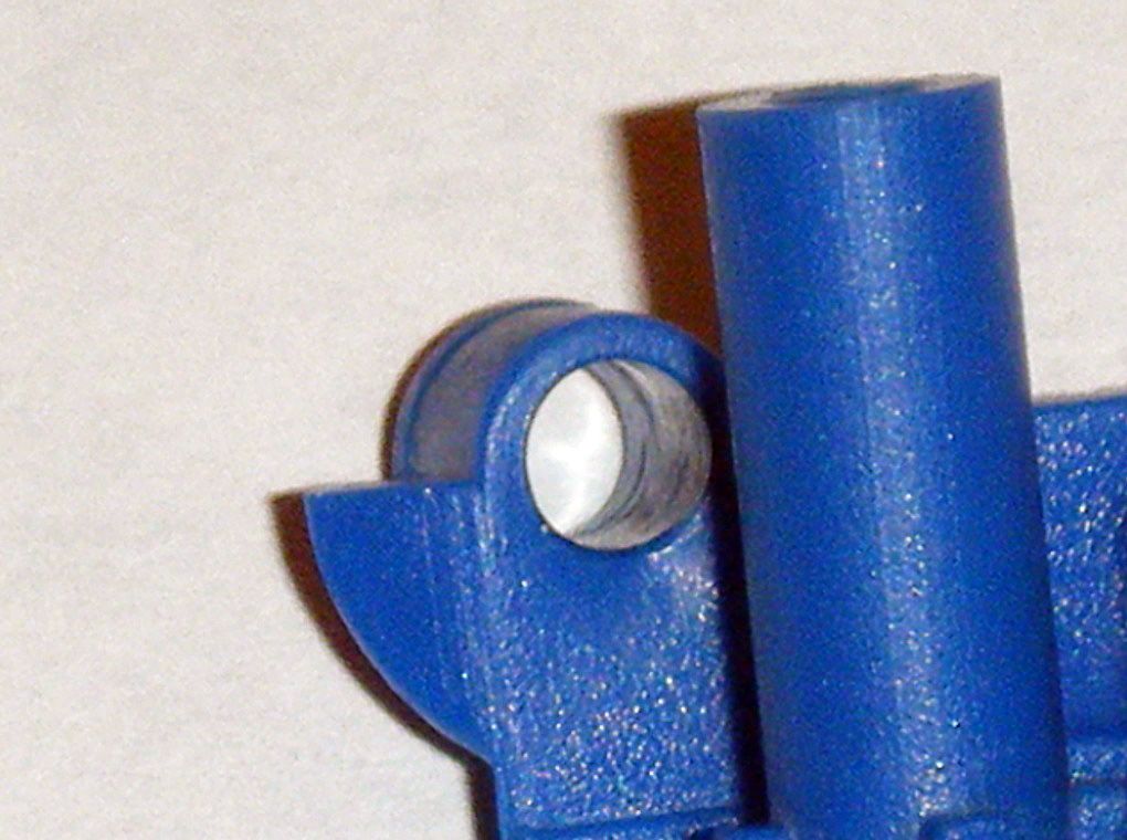
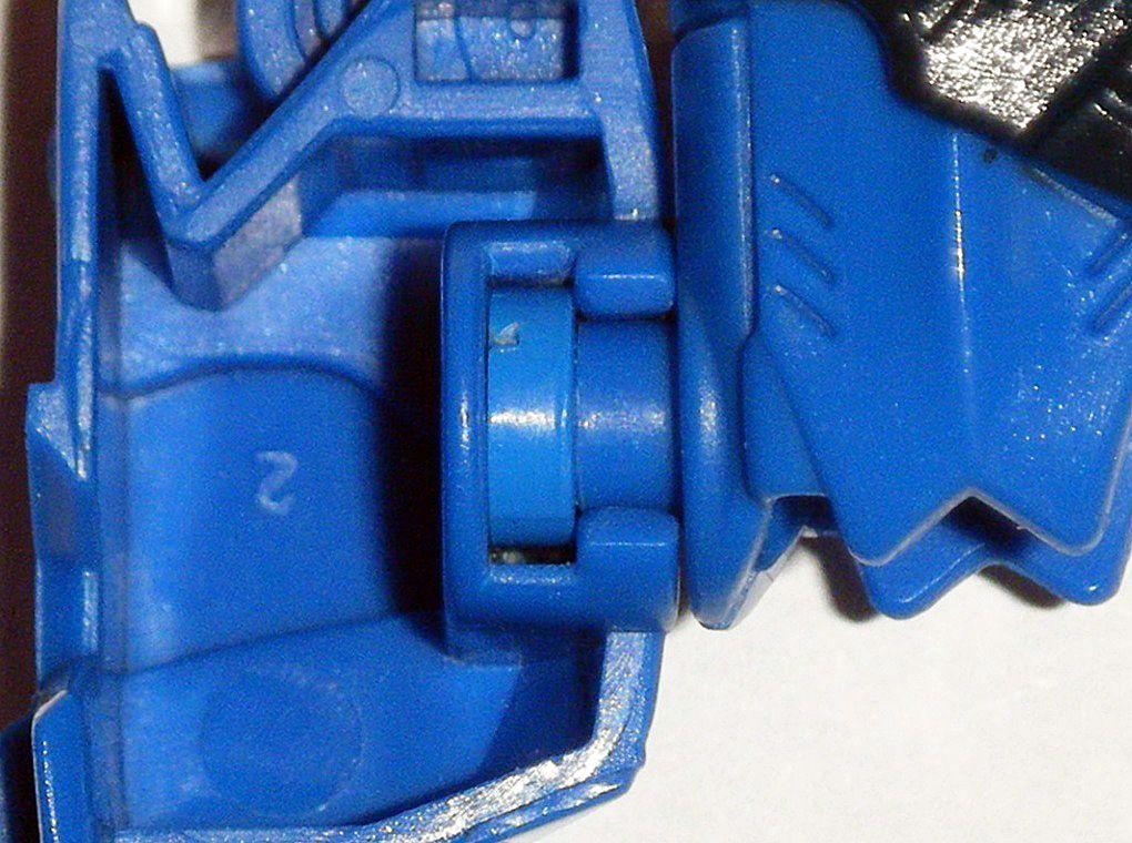
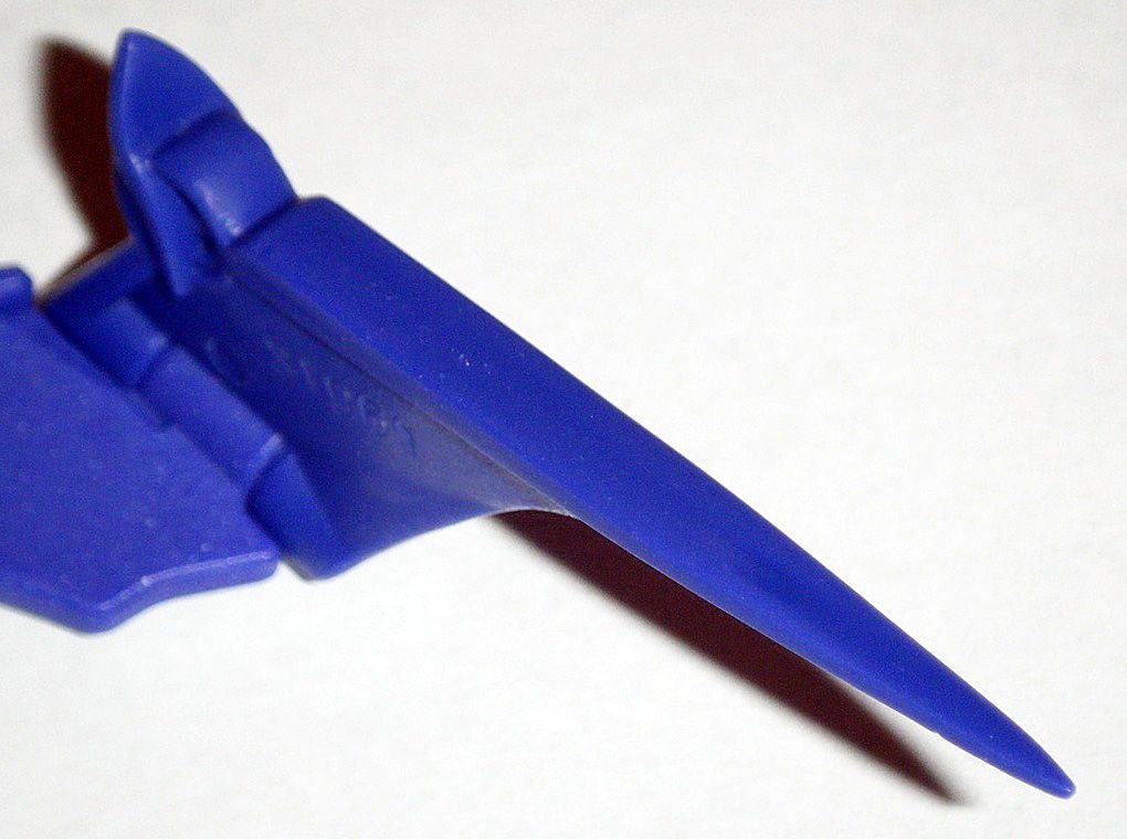
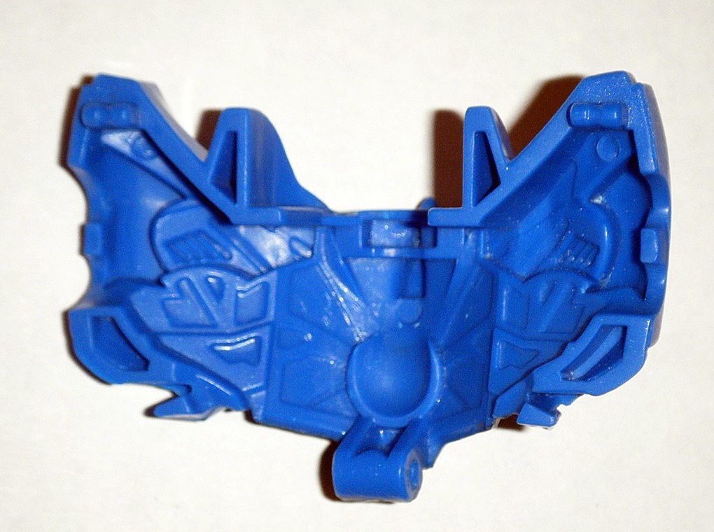
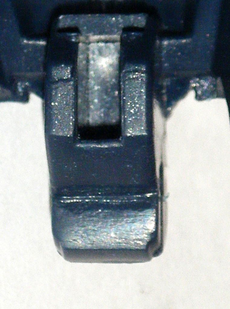
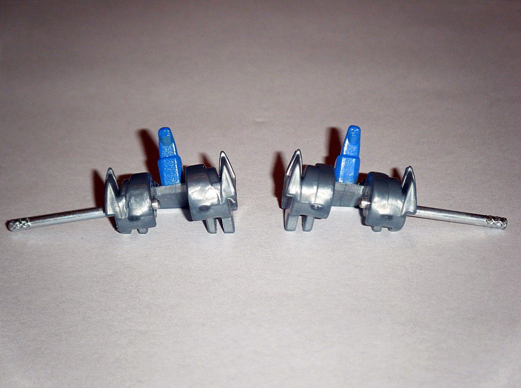
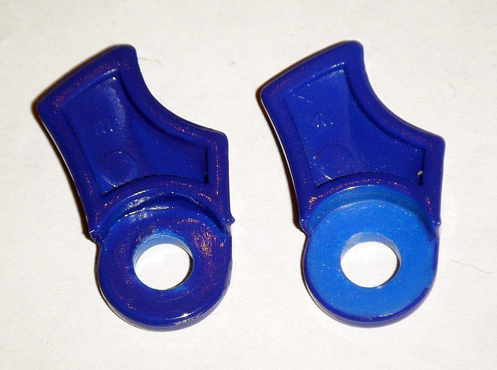
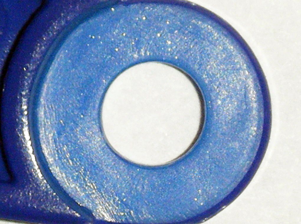
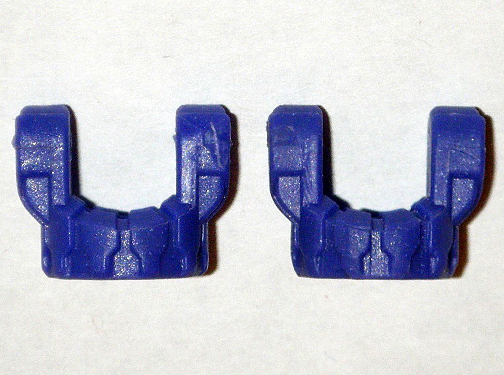
07) To give the joint a disk end, I used/did the following:
A
LEGO Blue Antenna Whip with Flag 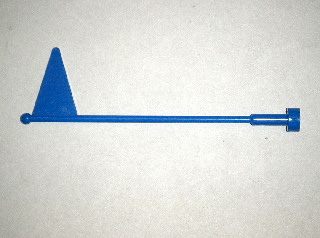
A
LEGO Black Round 1 x 1 Plate glued to the base of flag
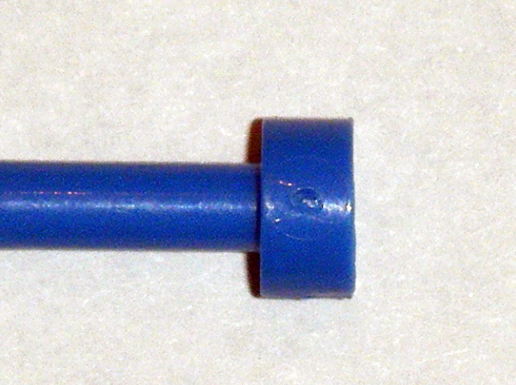
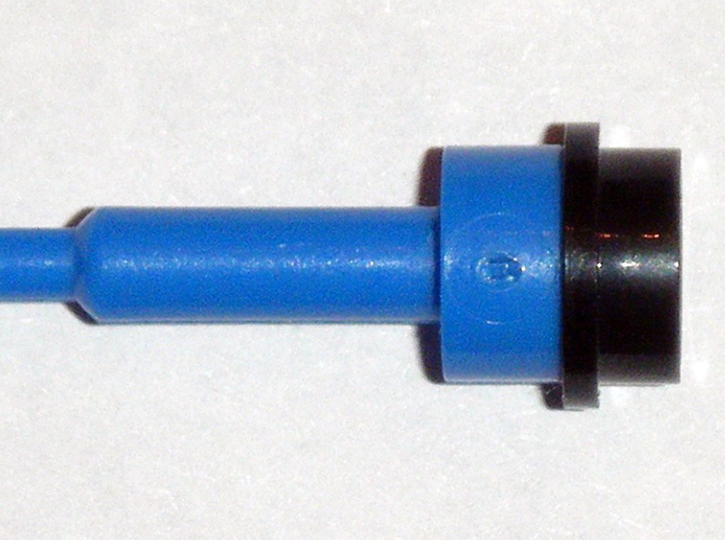
Sanded the end until it fit into the joint socket and cut offed the flag
Carefully shortened the joint peg until it fit on top of the joint socket and used wooden toothpick to spread
Gorilla Clear Glue inside drilled hole in joint peg
Treaded shoulder through antenna pole, pressed it onto the new joint disk, and waited an hour for it to cure.
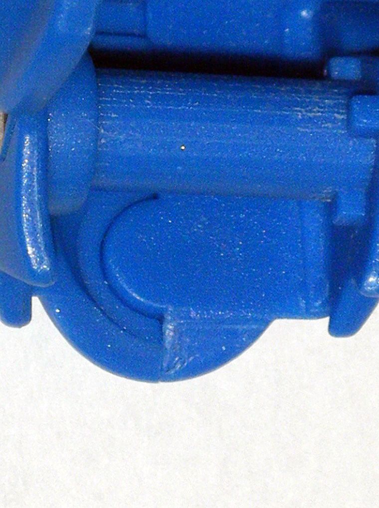
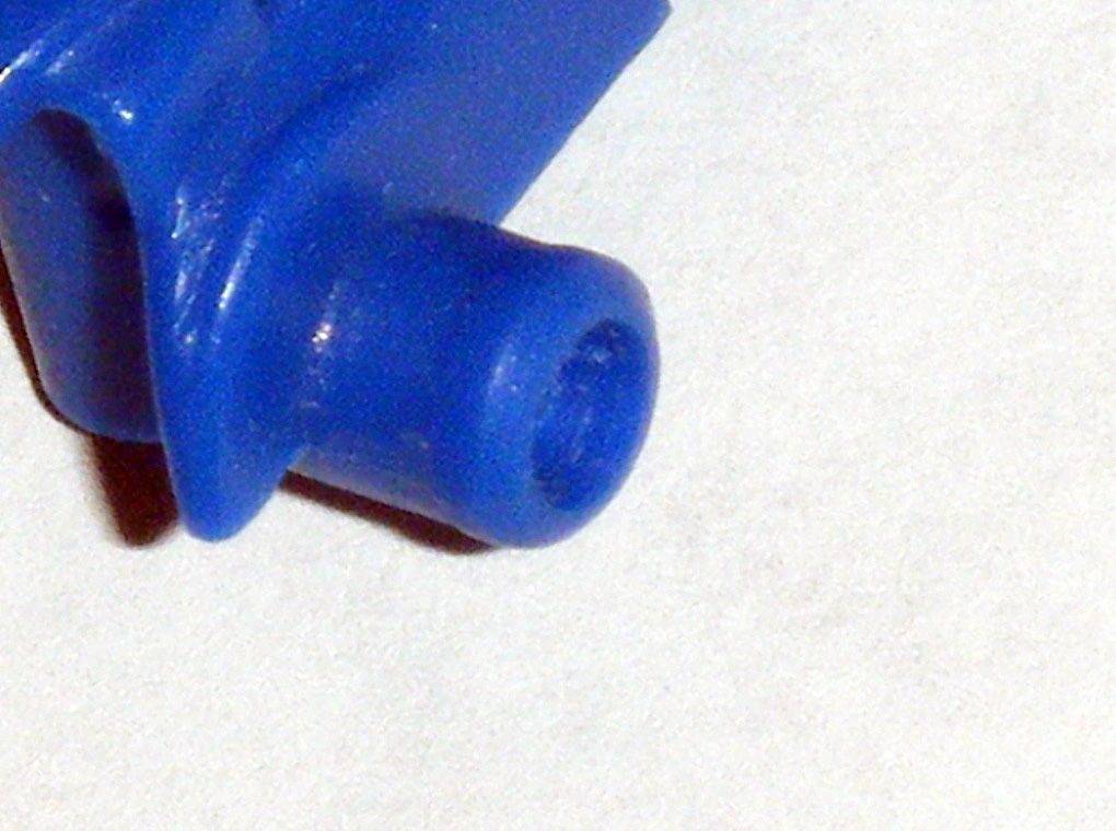
08) Screw holes of long shaft were reshaped with
Dremel 463 Rubber Polishing Tapered Point at low speed in order for screws to be placed in with greater ease:
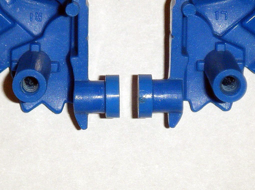
RESULT: Shoulder joint that are now tight, yet removable.
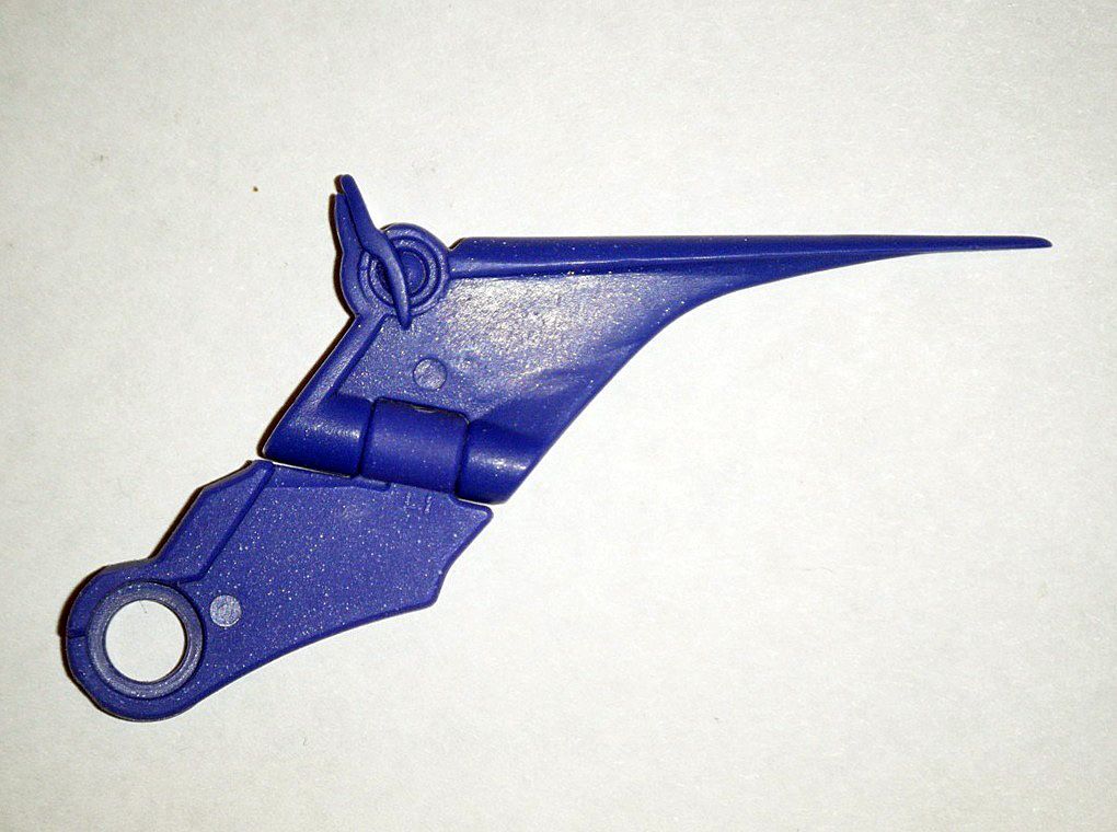
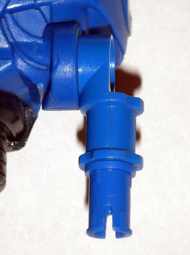
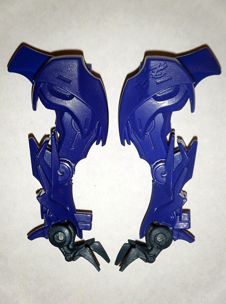
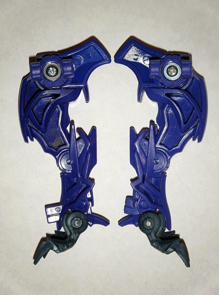
 D) ALTERNATE/ROBOT MODE ARMS:
Arms needed to be modified improve performance and become distinctive from
Predakings’
01) Halves of lower arms were separated, then the white Cybertronian inscriptions on outer half were removed with
3M 800 Imperial Wetordry Sandpaper then polished down area:
02) On inner half, spikes on back were cut off and outer long crest was reshaped:
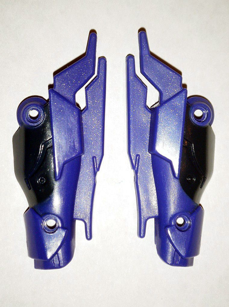
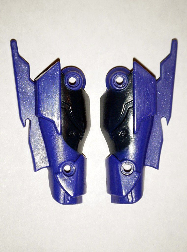
03) Area around joint hole was carefully reshaped:
04) With a
wooden toothpick,
Gorilla Clear Glue was applied to the inside of the upper disk joint and left to cure for a week:
05) Upper disk joint is now tight and held in place:
06) Area on top near wrist was smooth and polished down:
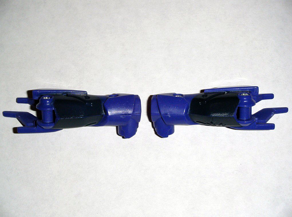
07) Claws were carefully reshaped into points:
08)
Gorilla Clear Glue was applied to wrist joint and was left to cure for a week. After said week, dried glue was carefully sanded and polished down in order to achieve the appropriate level of tightness:
RESULT: Arms that have tight joints, better movement, and pointed claws.
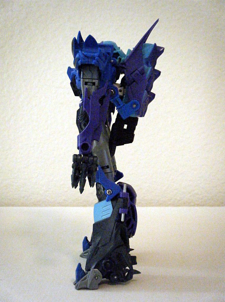
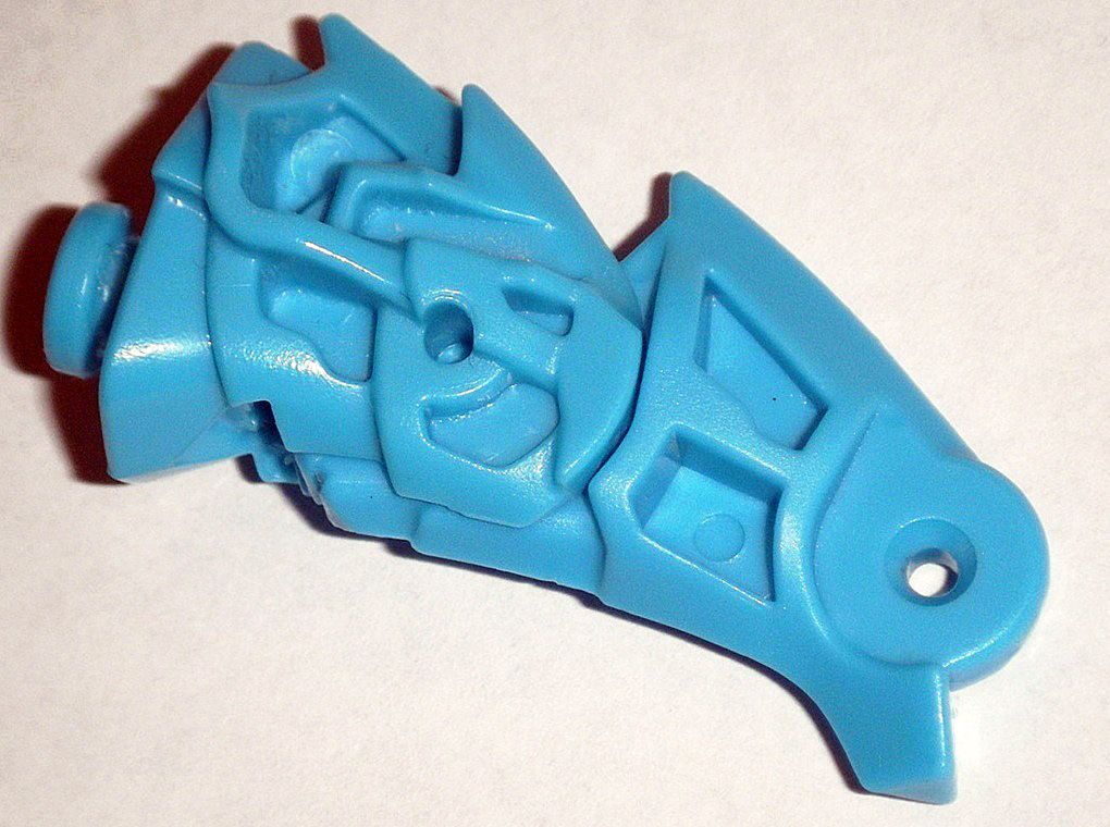
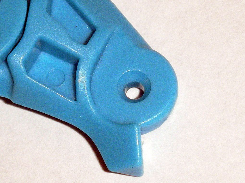
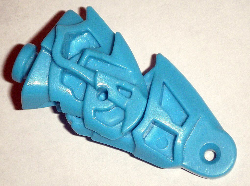
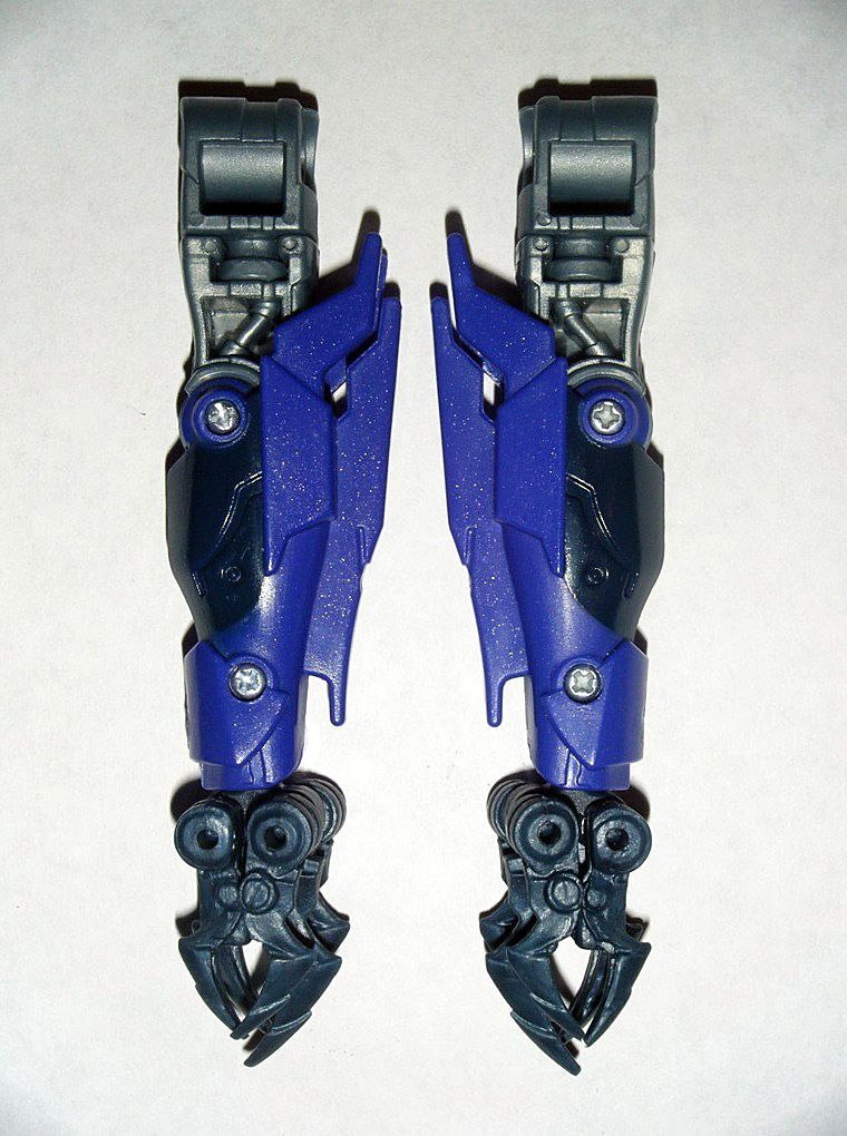
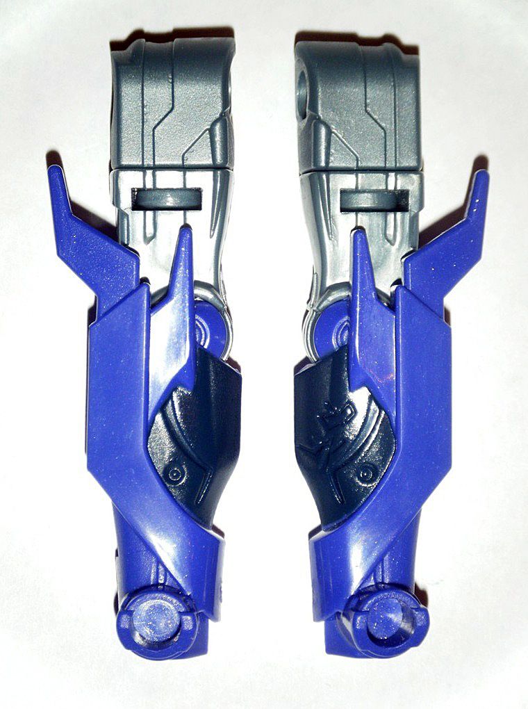
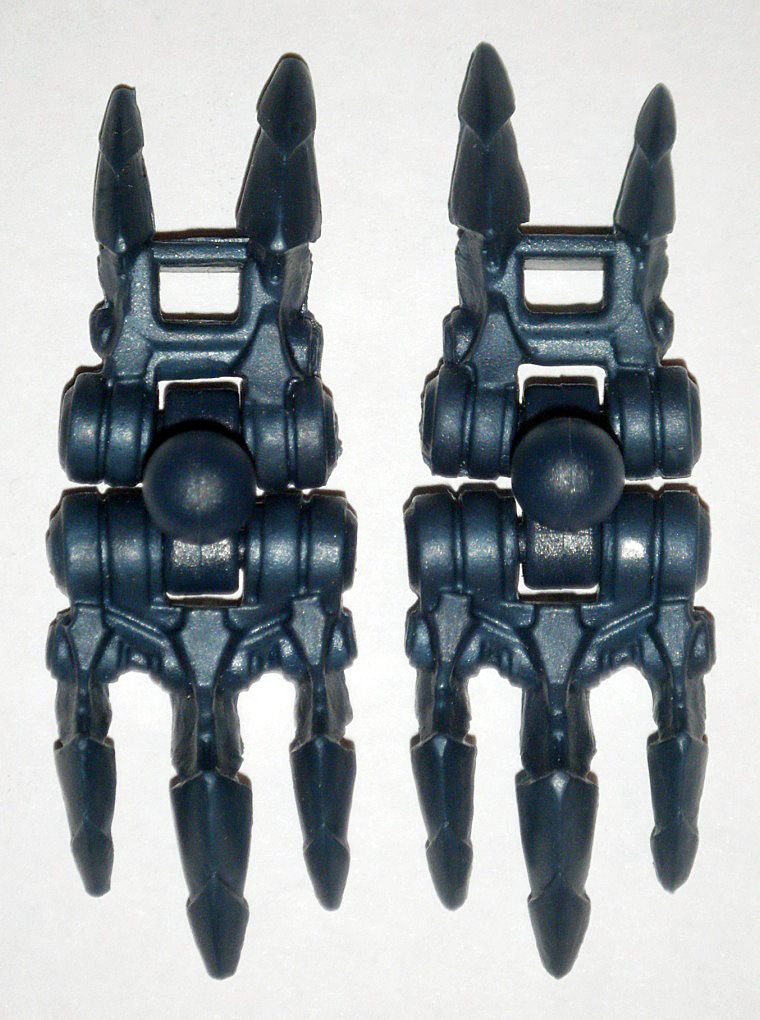
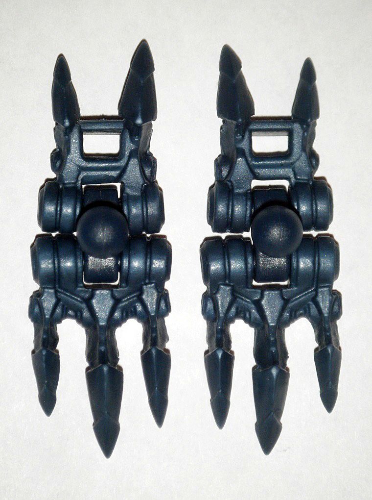
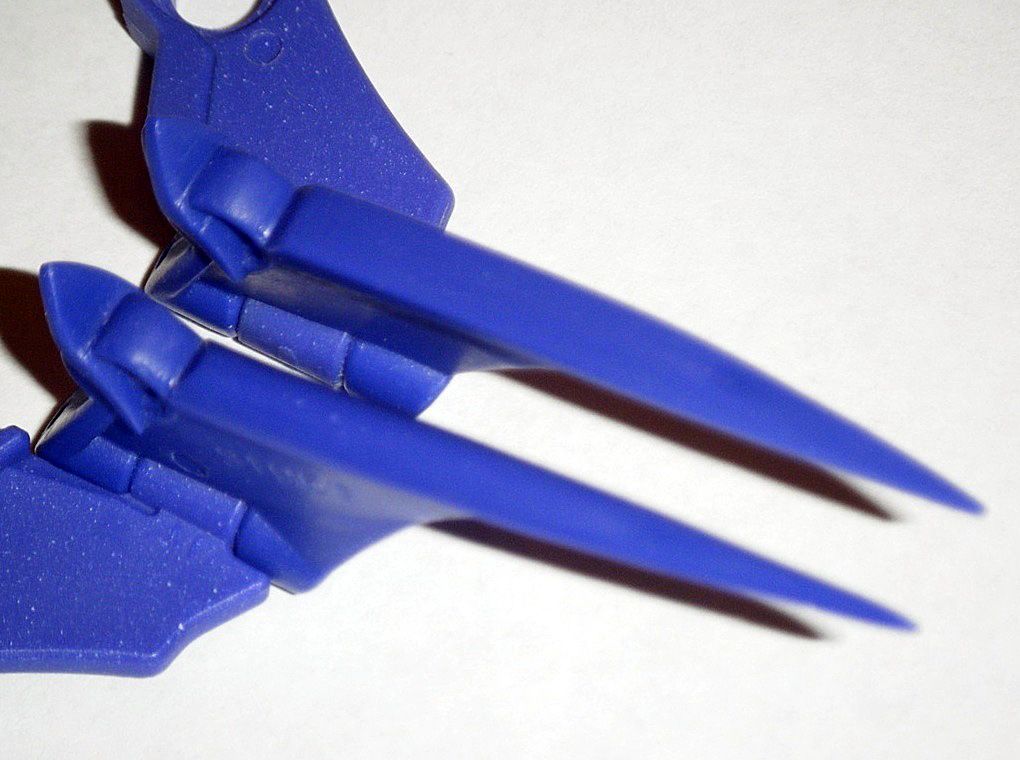
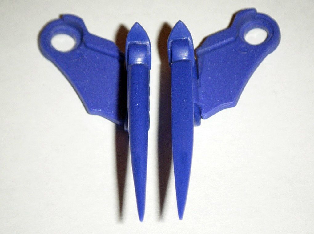
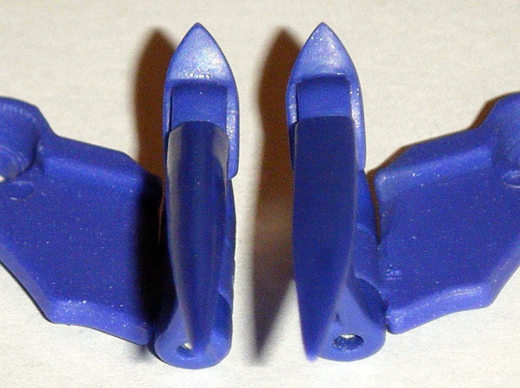
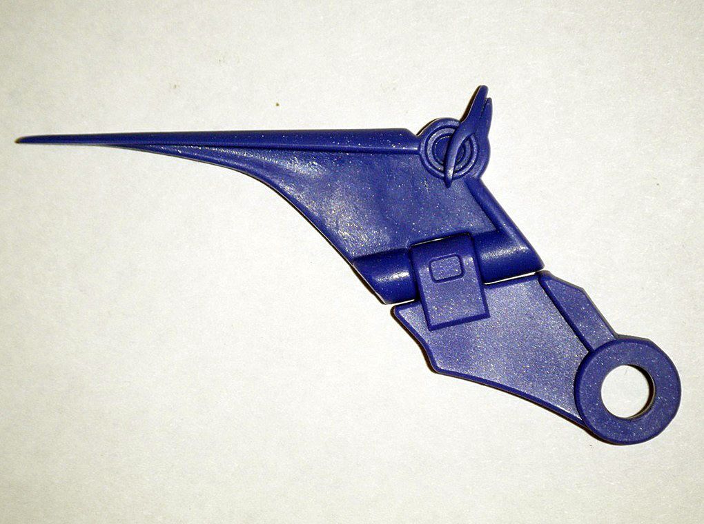
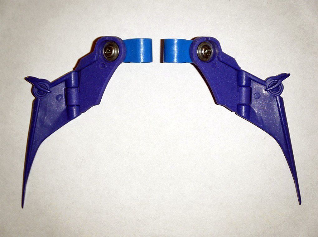
 E) WINGS:
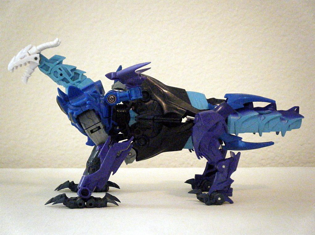
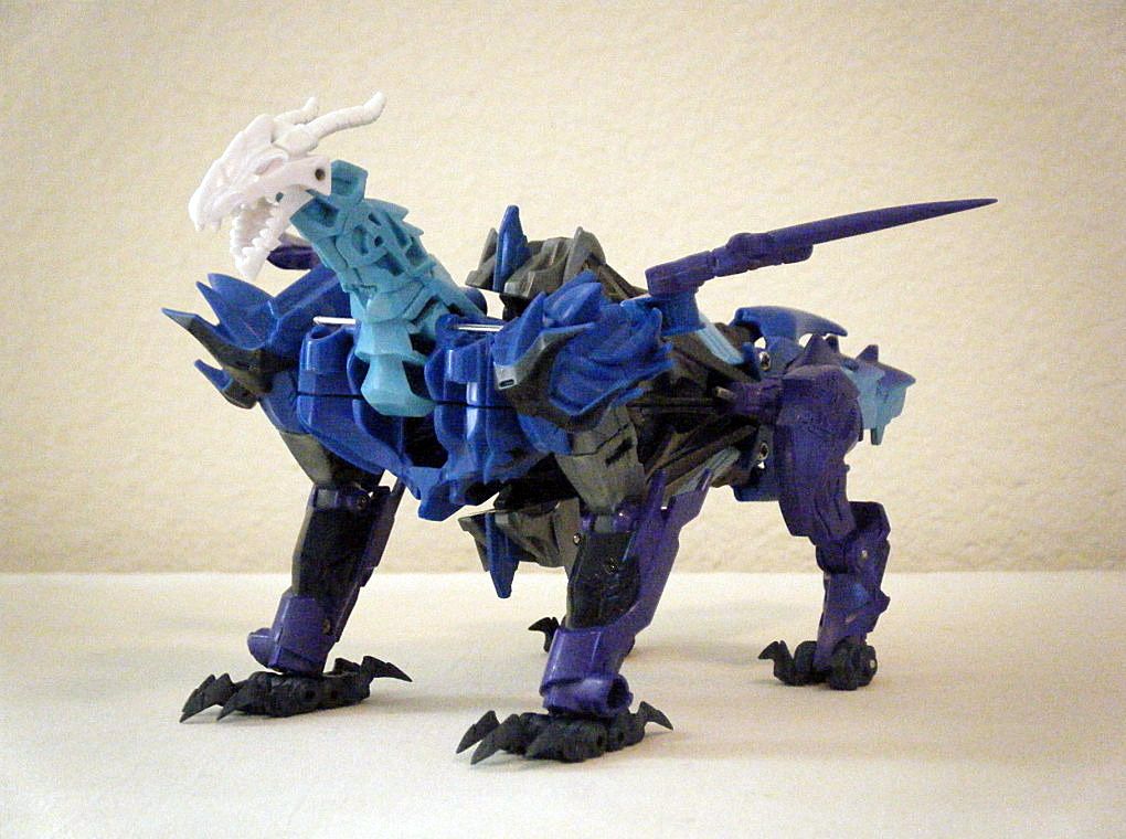
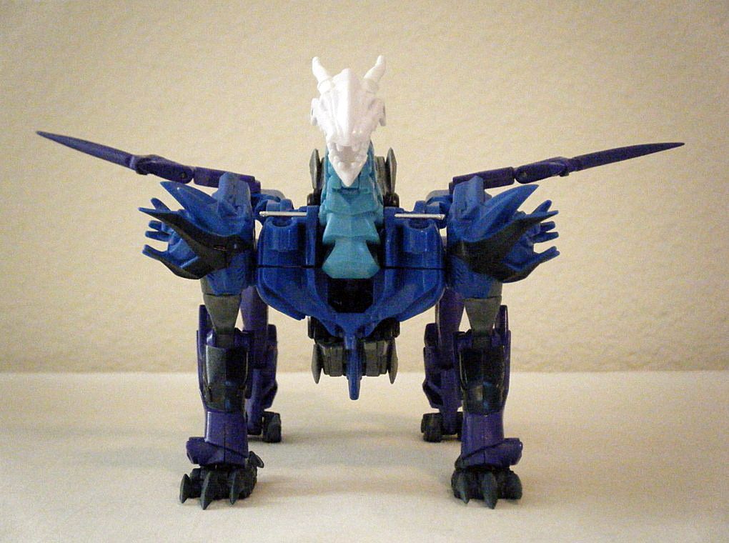
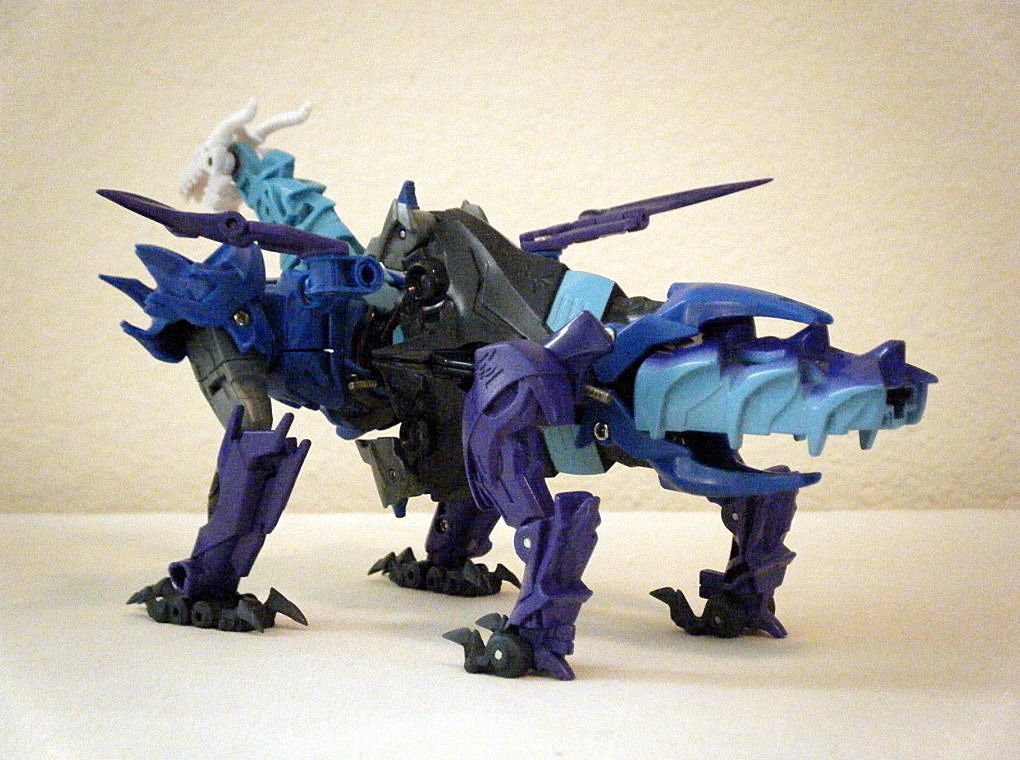
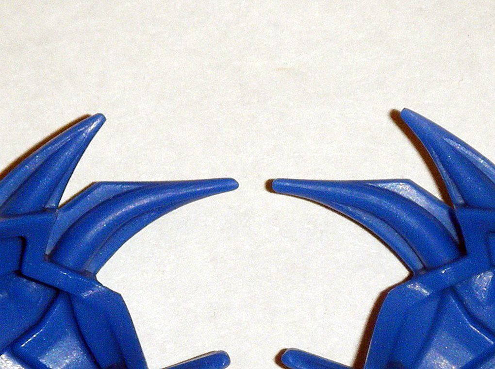
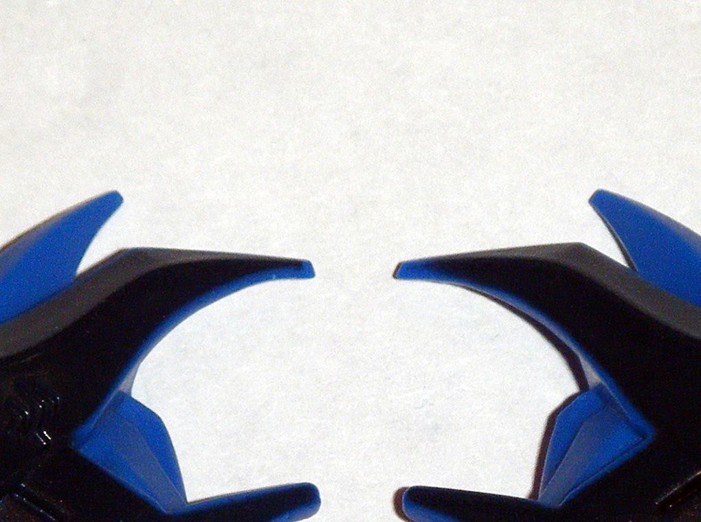
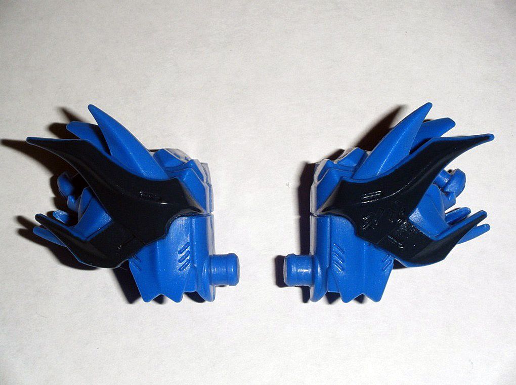
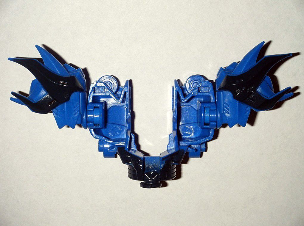
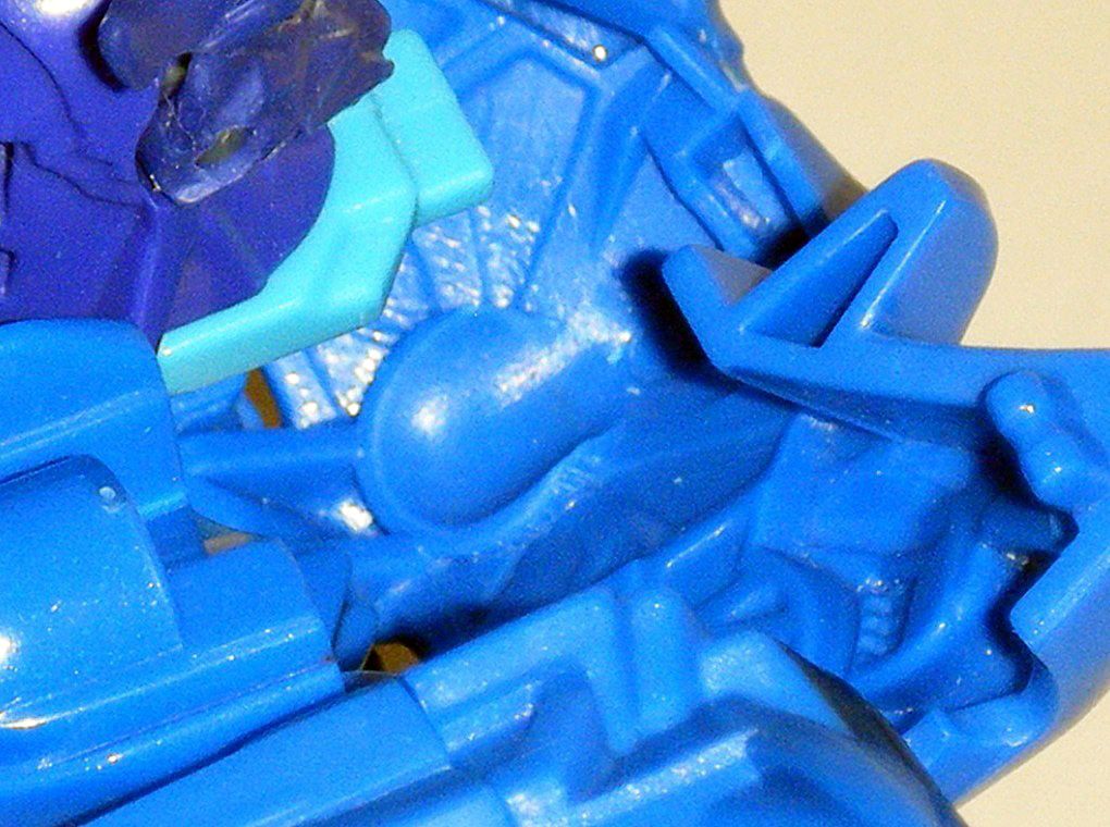
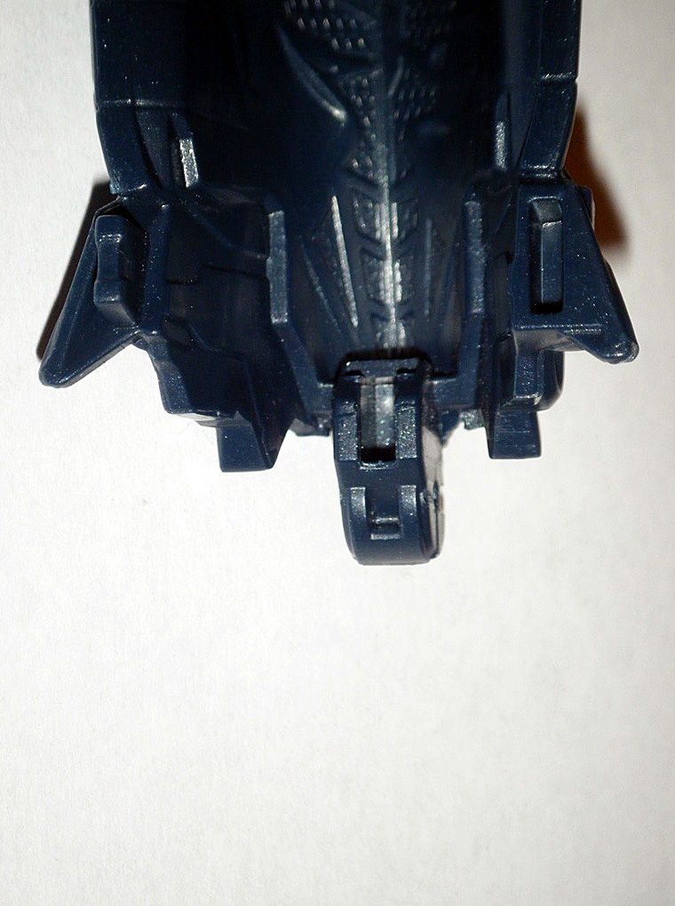
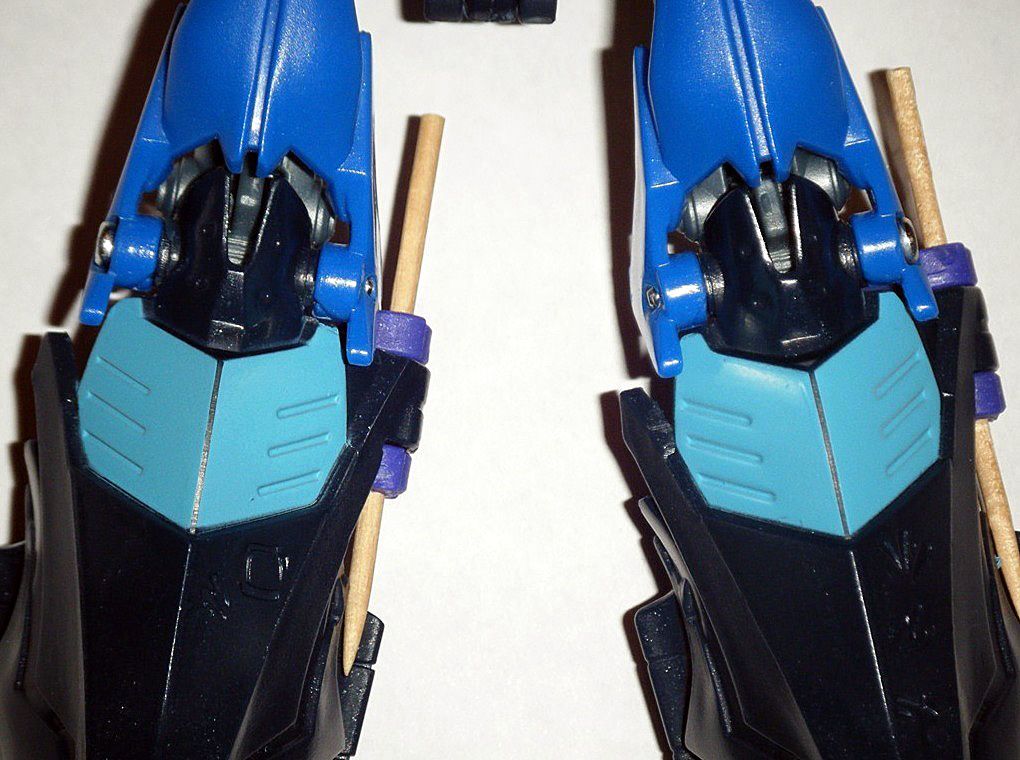
As a marine/sea dragon
Predacon,
Dreadnought’s wings needed to be extensively modified for him to function in water.
01) Wings halves were separated and shorter half was submerged in
91% Isopropyl Alcohol for an hour or two in order to remove the silver paint apps and black serial number:
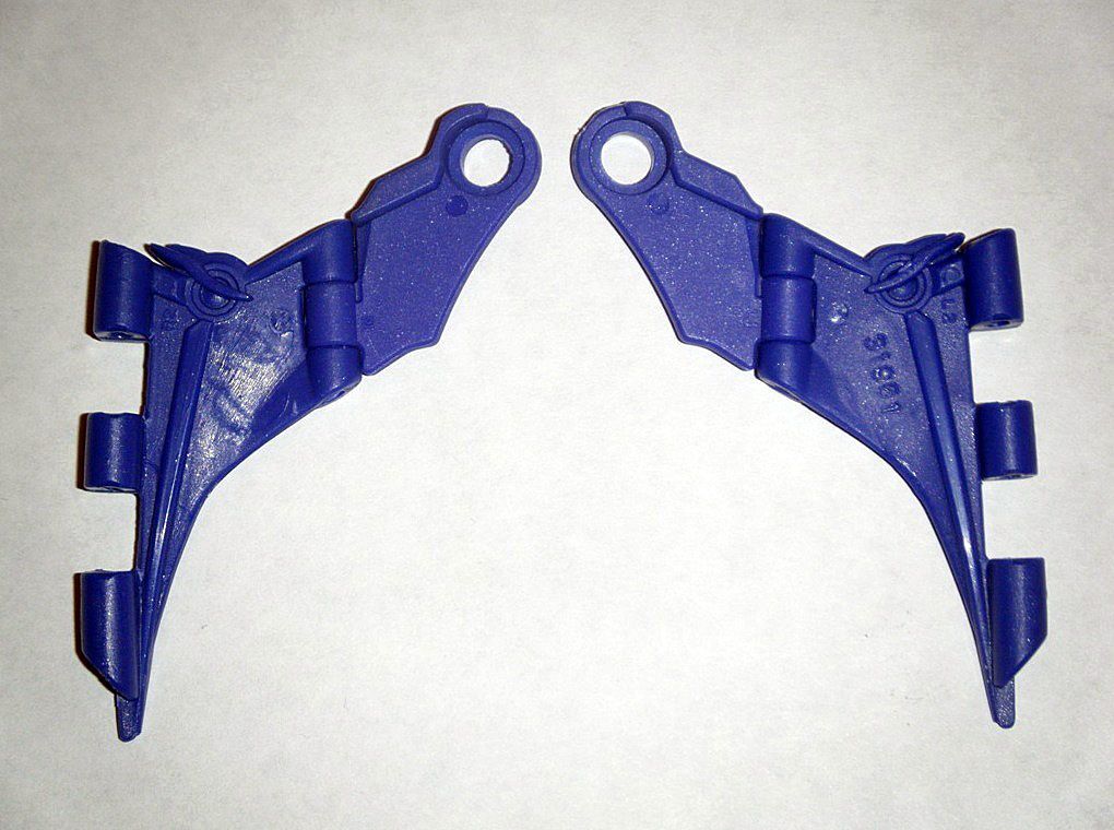
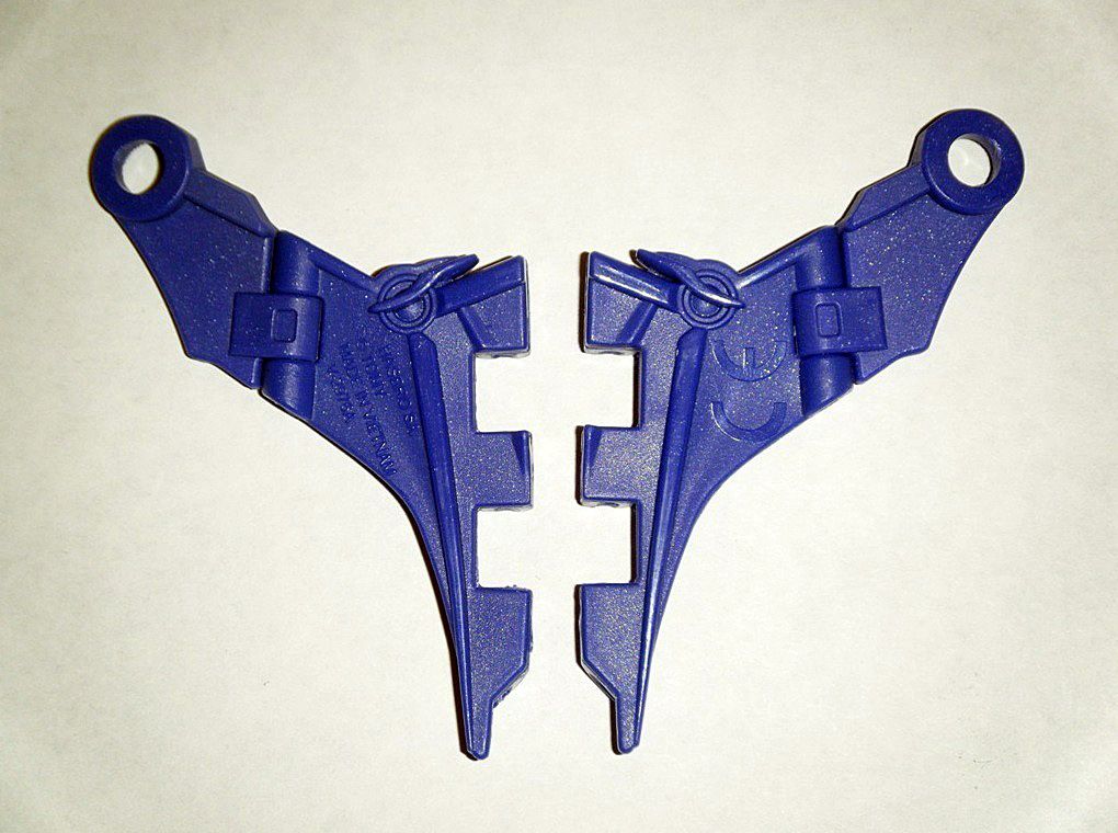
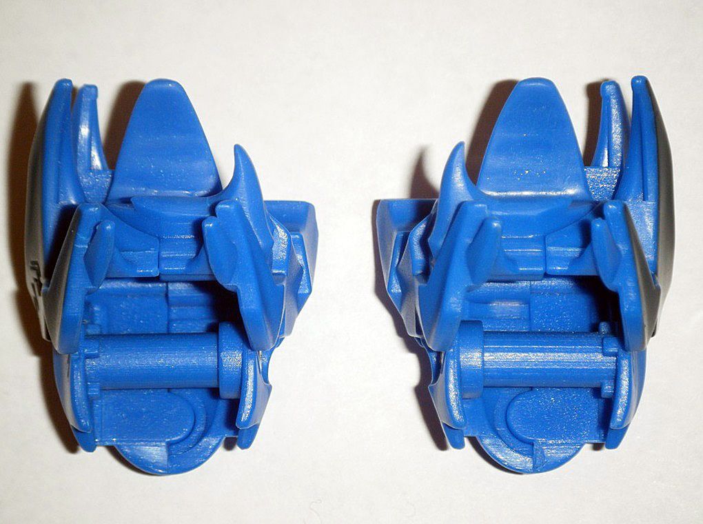
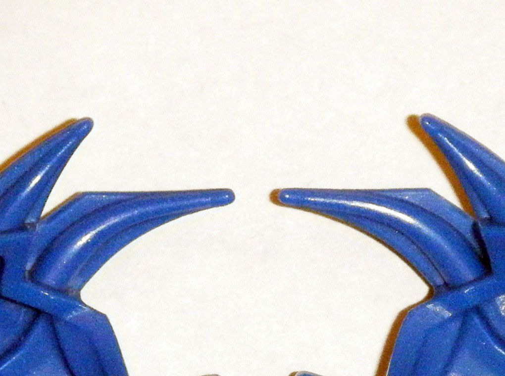
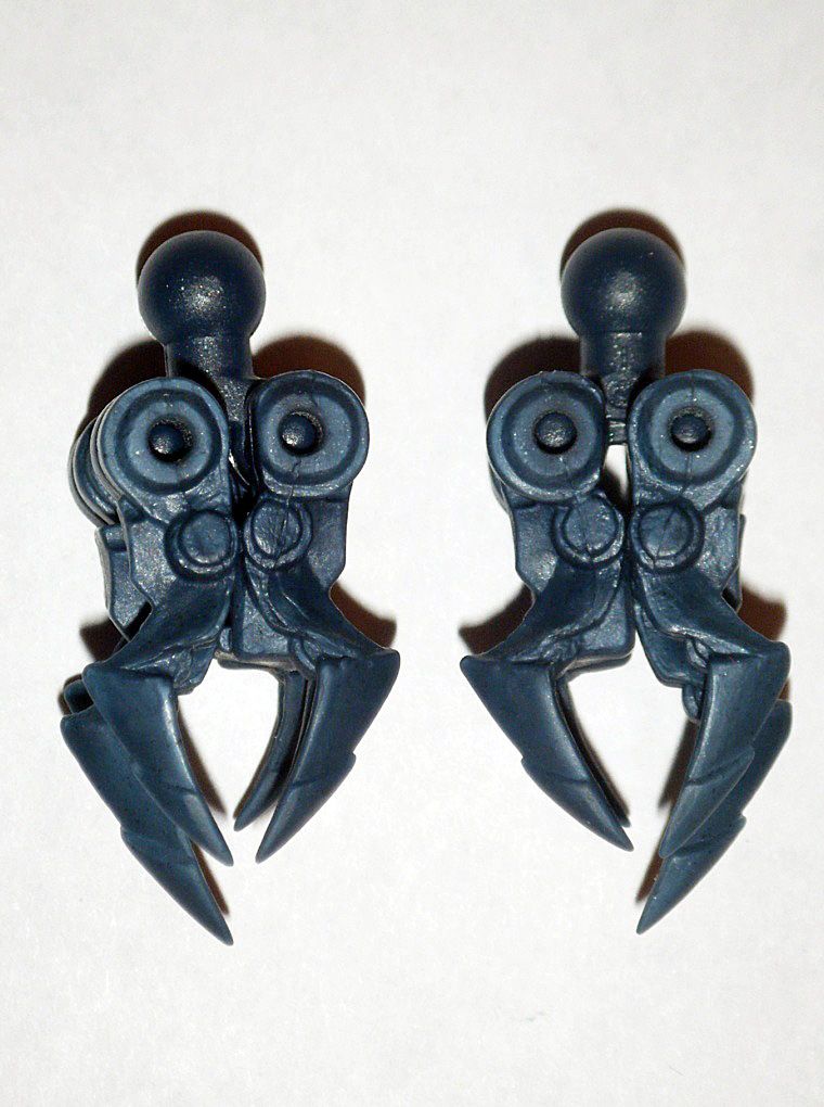
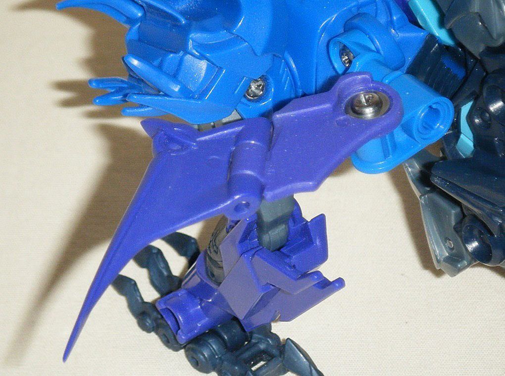
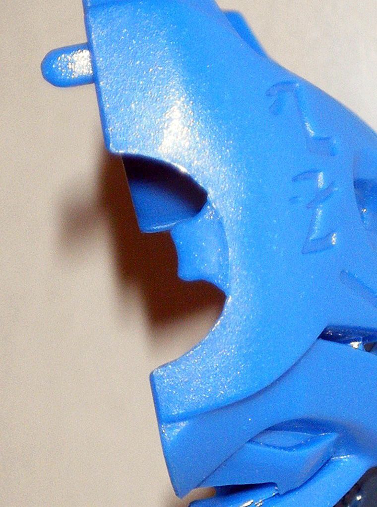
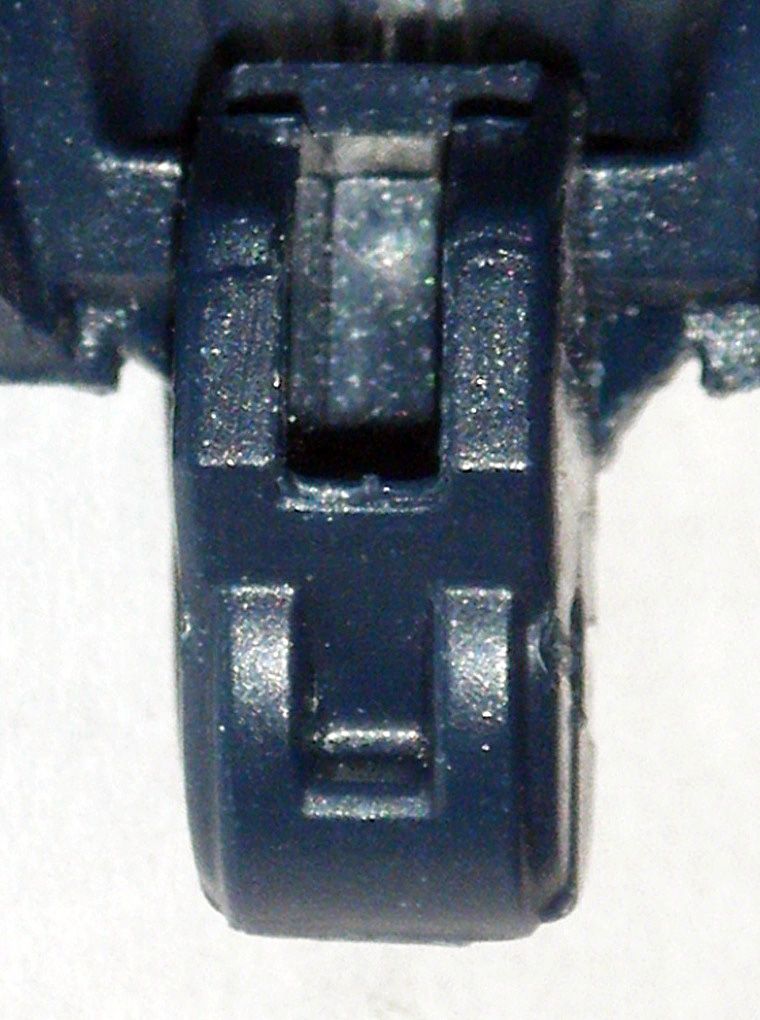
02) Hinge mount was carefully removed, sanded and polished down to reshape into wing finger. CE logo on left wing and raised lettering on right wing were sanded down and area polished. Finally, spikes were reshaped into points:
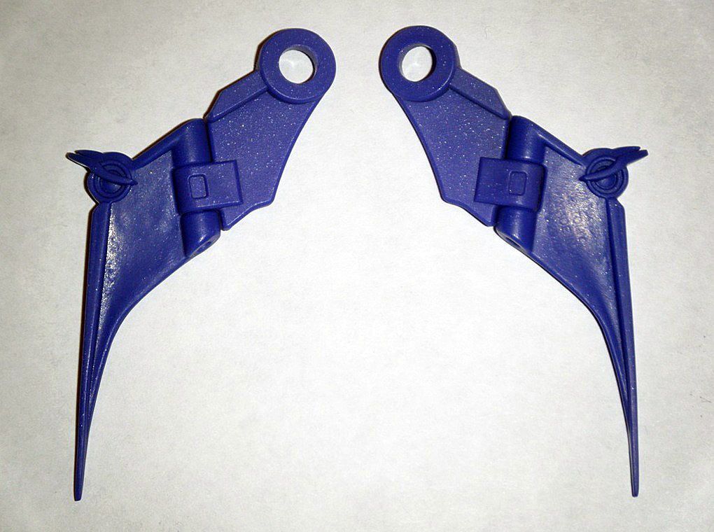
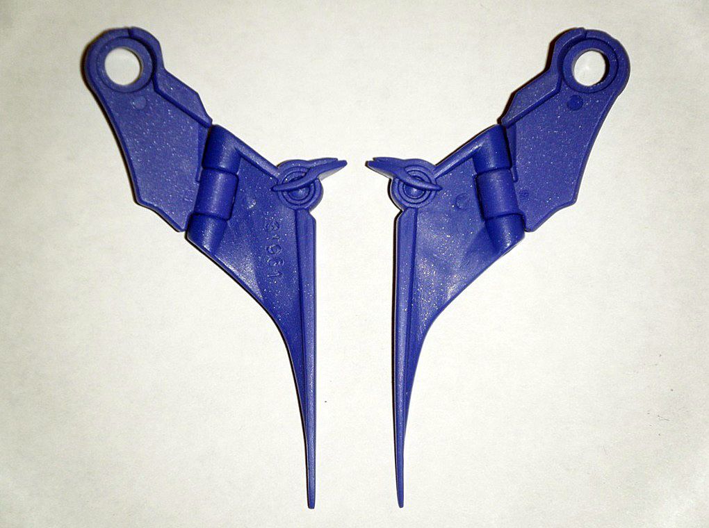
03) Wing “finger” was rounded and smoothed out to make it more hydrodynamic:
04) Used
soldering iron to melt down the etched serial number on right wing, then sanded and polished it down:
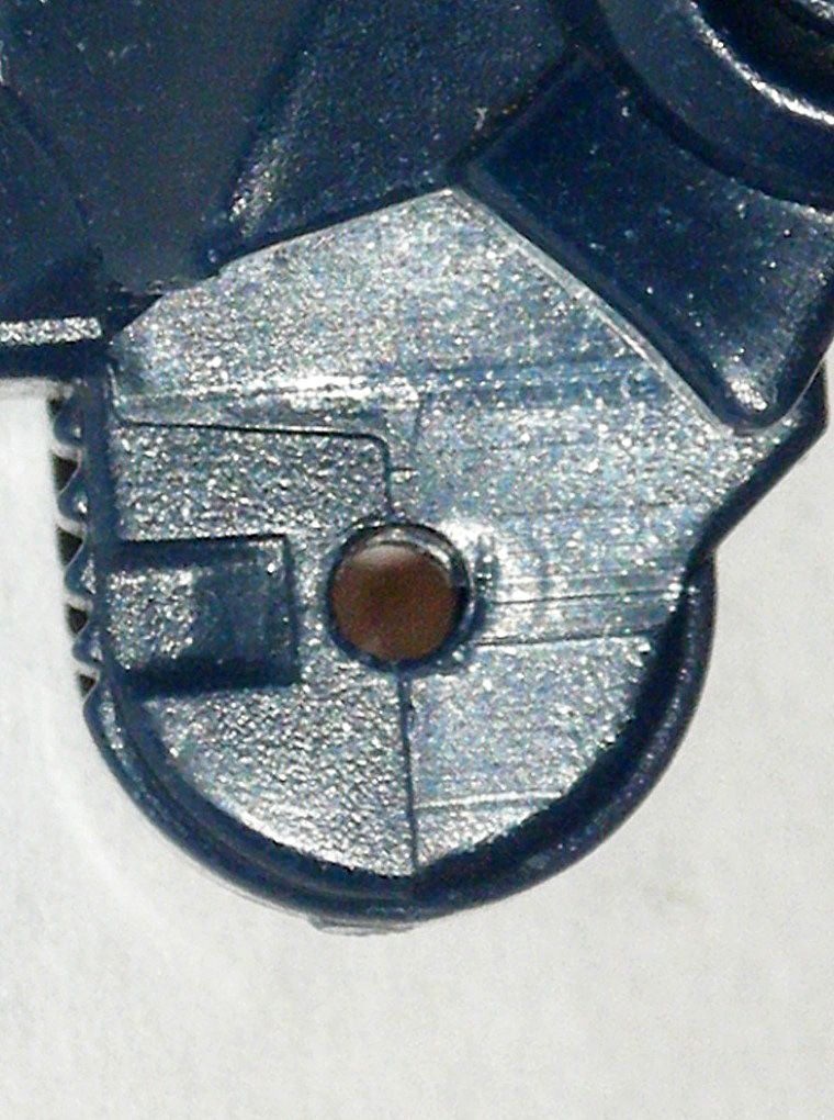
05) Used an
ACE 5/64” drill bit at low speed to widen holes in back pegs for new Philips washer head screws from arms of
ROTF Voyager Ironhide, which were cut offed and shortened to fit completely through the hole:
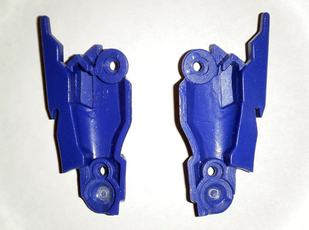
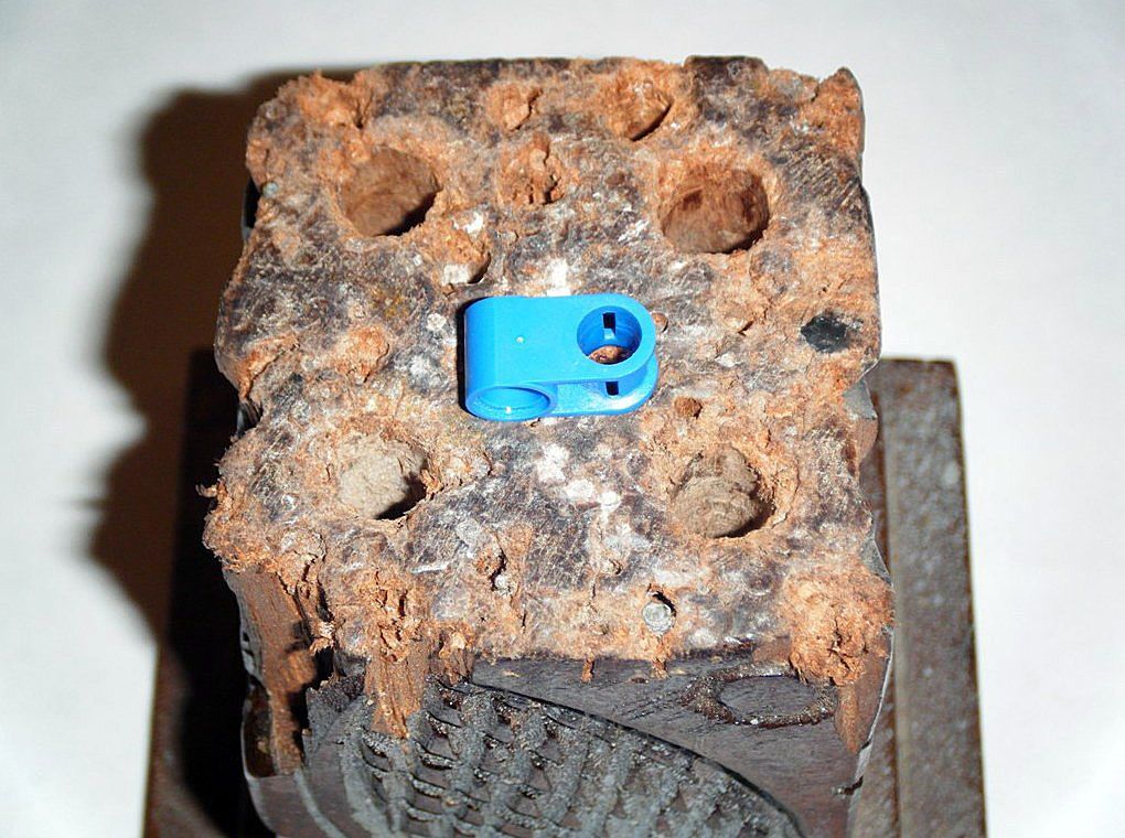
06) The first half of the new wing mounts were created for the wings using
LEGO Technic Blue Axle and Pin Connectors with Smooth Toggle that were first modified to fit on the back pegs with the new
Philips washer head screws holding them in place with a
LEGO Technic Blue Axle Pin with Friction Ridges Lengthwise glued on via the axle end:
07) The second half of the new wing mounts were first created from
LEGO Technic Blue Axle and Pin Perpendicular Connectors:
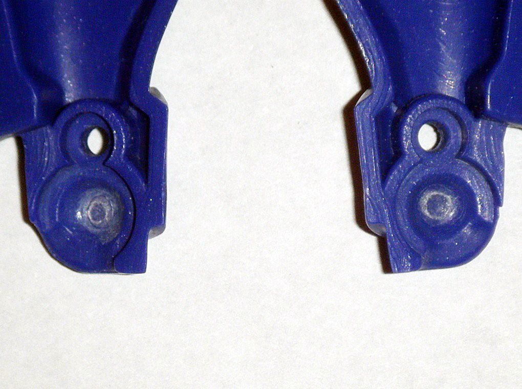
08) Used a
LEGO Technic Black Pin with Friction Ridges Lengthwise with Center Slots to link connectors side by side in order to sand down one side with emery board:
09) To create the pegs that hold the wings in place on the blue connectors, the screw shafts from a pair of junk
Cryofire Predaking shoulders were widened carefully with an
ACE 5/64” drill bit at low speed to accommodate a pair of new
Philips washer head screws from a junk
ROTF Leader Optimus Prime. Once the screws were in place, the shafts were cut off and the purple wings threaded on:
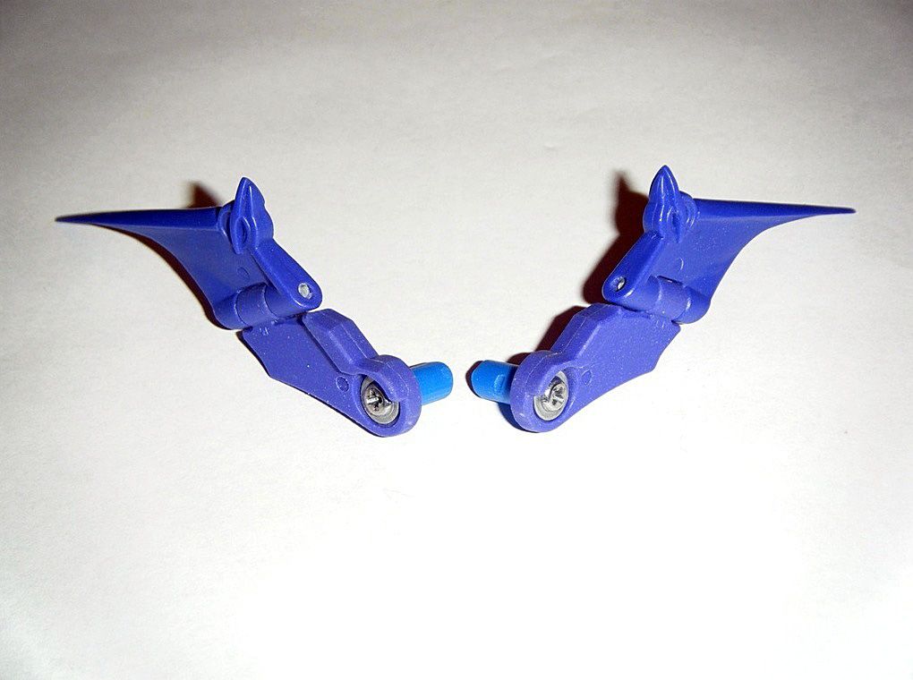
10) After carefully widening the pin hole of the connector and spreading
Gorilla Clear Glue inside, I used an old wooden pencil holder with drilled holes and a
Philips head screwdriver to press the screw shaft with wing and washer head screw through hole:
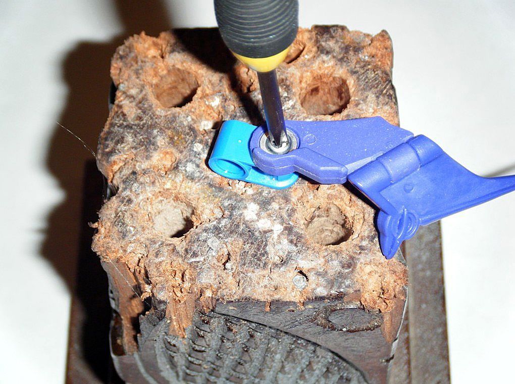
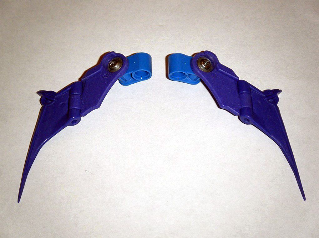
11) After leaving it to cure for an hour, the washer head screw and wing were removed and the bottom of the second half of the new wing mount was sanded and polished down:
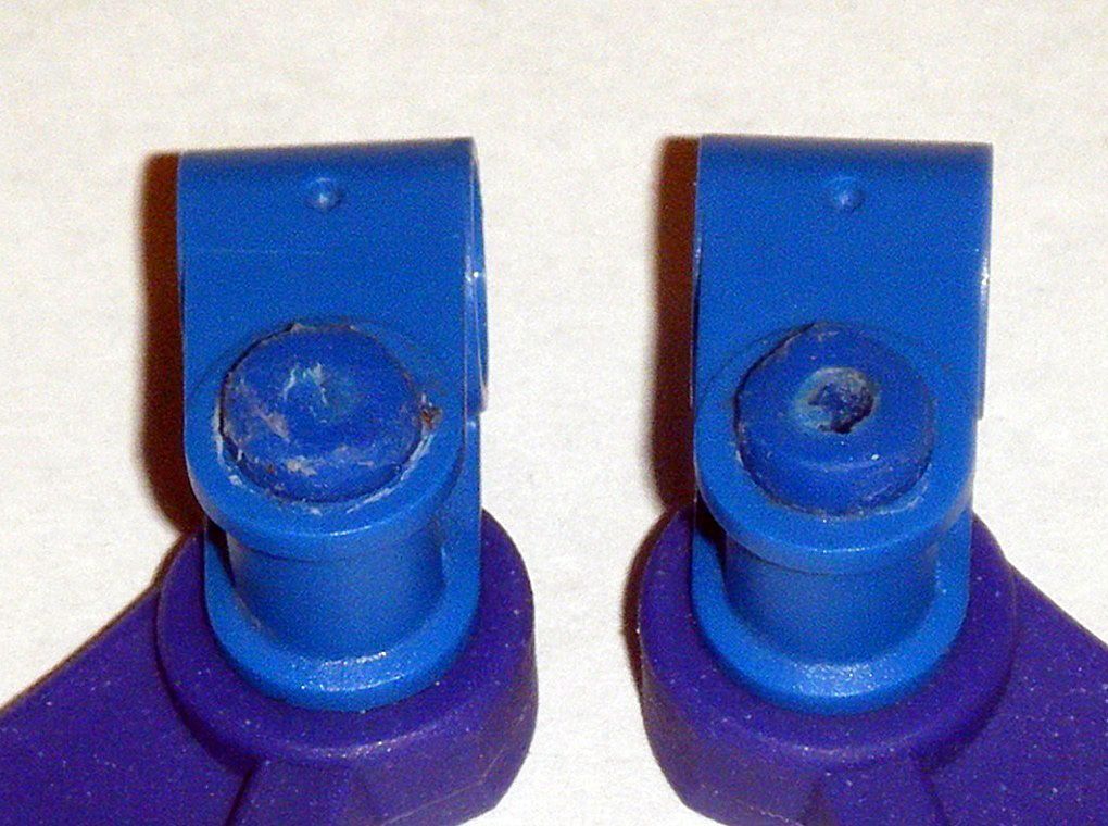
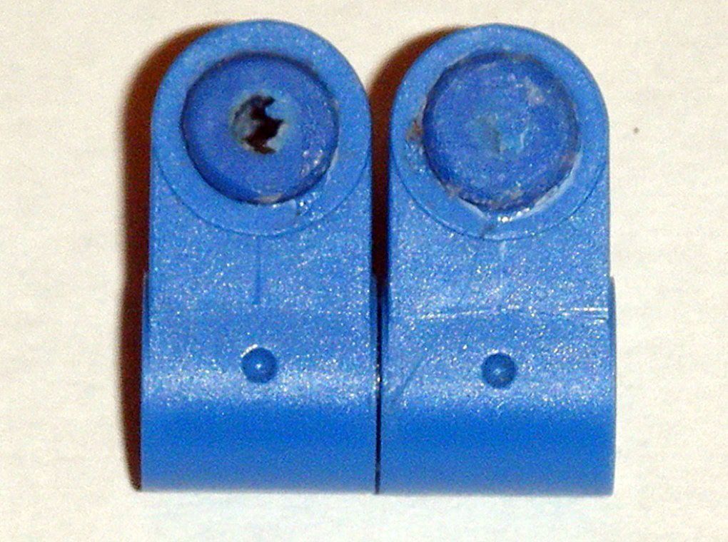
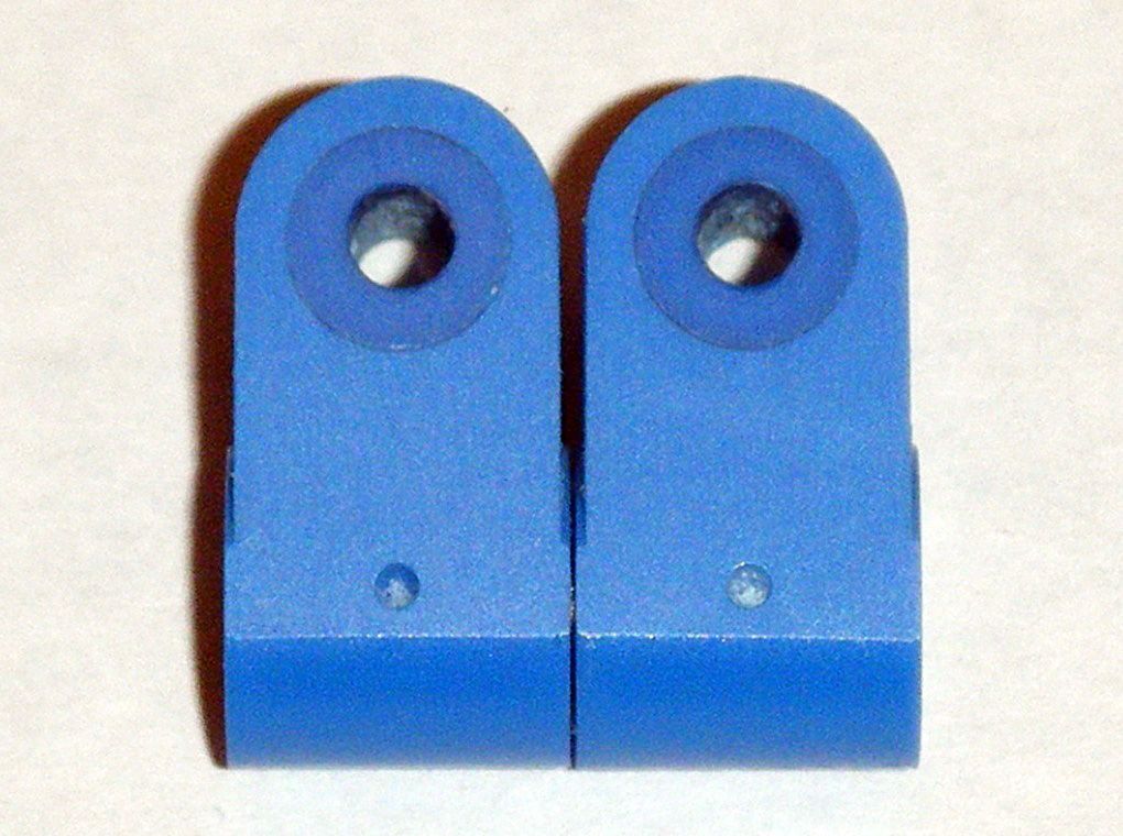
12) The numbers and LEGO logo inside the connectors were removed with a
Dremel 108 Engraving Cutter:
13) Wings and washer head were reinstalled. Second half completed and attached to first half:
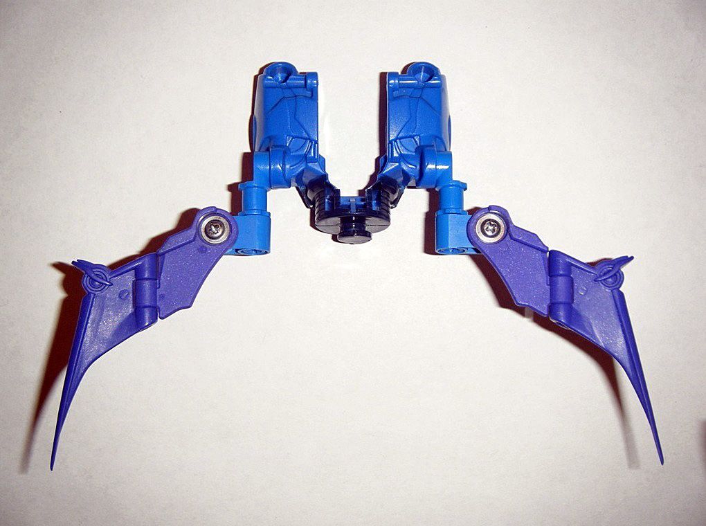
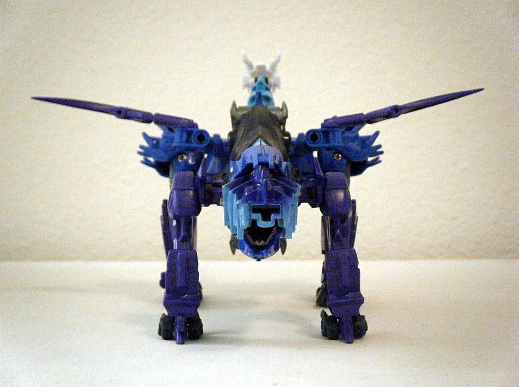
RESULT: Shortened wings that work like the diving planes on a submarine.
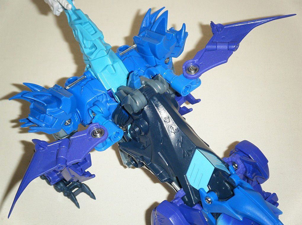
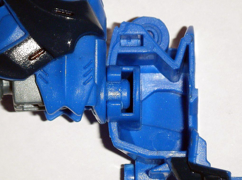
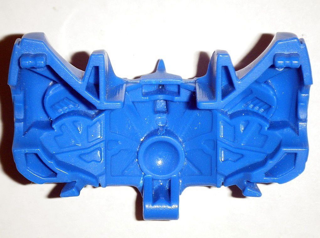
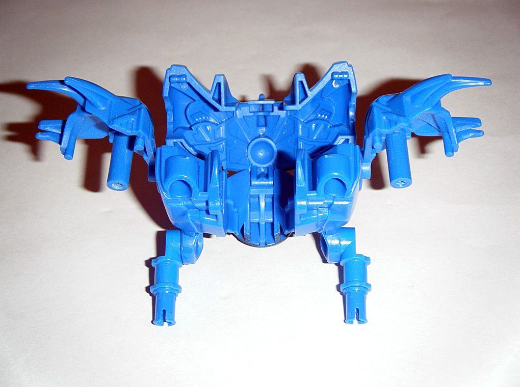
 F) ALTERNATE/ROBOT MODE BACK & ABDOMEN:
To modify this section, the wings and their hinge mounts were removed:
01) The upper interior was carefully sanded and smoothed down in order for the chest piece to close down completely:
02)
Gorilla Clear Glue was applied to the left and right rivet holes on the inside and left to cure for a week, then sanded and smoothed down carefully so that the alternate mode neck can be held in more securely:
03) Used
X-ACTO #11 Classic Fine Point Knife to scrape of some of the dark blue paint on the lower abdomen and the plastic ridges inside were shortened to prevent the horns of the robot mode head from bending when transforming:
04) Some of the plastic on the floor of the abdomen was carefully sanded and polished down to further prevent the horns of the robot mode head from bending when transforming:
RESULT: The alternate mode neck will not move loosely anymore and horns of the robot mode head will not bend when transforming.
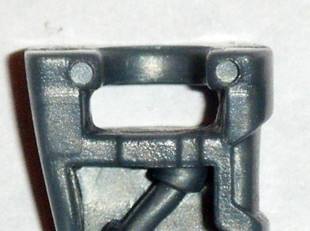
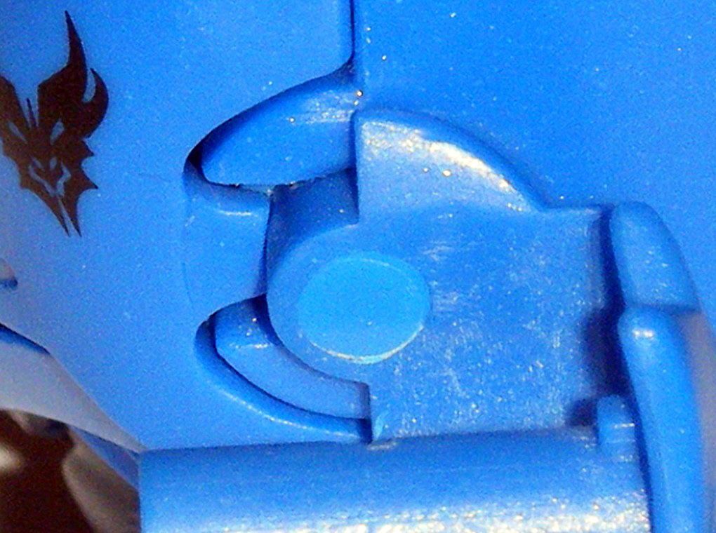
G) ALTERNATE/ROBOT MODE CHEST:01) The opening and tabs on the left and right sides the fit onto the shoulder joint socket the held the shoulder piece in place were carefully widened, shortened, and polished down to allow the chest piece to close completely onto the back/abdomen piece. In addition, the interior of the chest piece was carefully sanded and polished down to achieve that result as well:
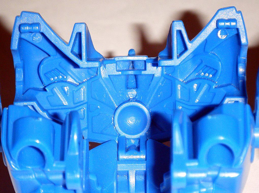
02) The bowl-shaped area inside the chest piece was carefully sanded down at the top to prevent the forehead horn on
Dreadnought’s robot head from bending onto it when transforming and when in alternate mode:
03) The crest on the top of his chest was carefully reshaped and smoothed out to give it a more hydrodynamic look:
04) Used an
X-ACTO #11 Classic Fine Point Knife to scrape off some of the dark blue paint from the upper abdomen area of the chest piece to give it a different look:
RESULT: Chest piece has a look that’s unique to
Dreadnought and won’t hinder the movement of the robot mode head when transforming and deform the robot mode head’s forehead horn when in alternate mode.
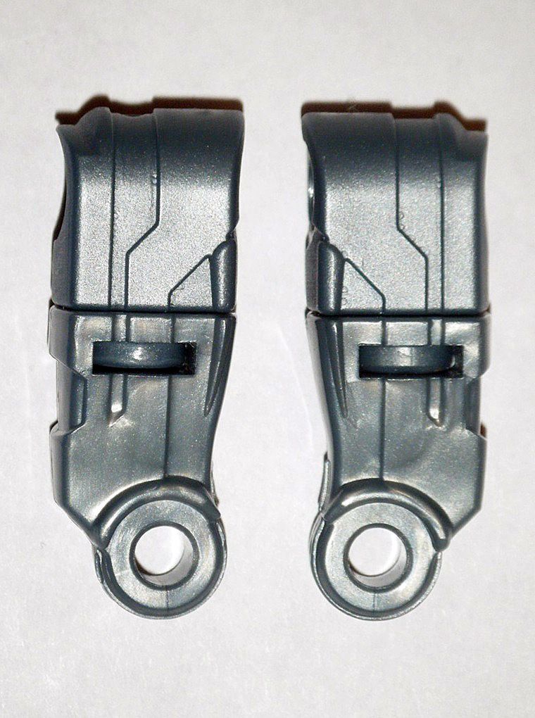
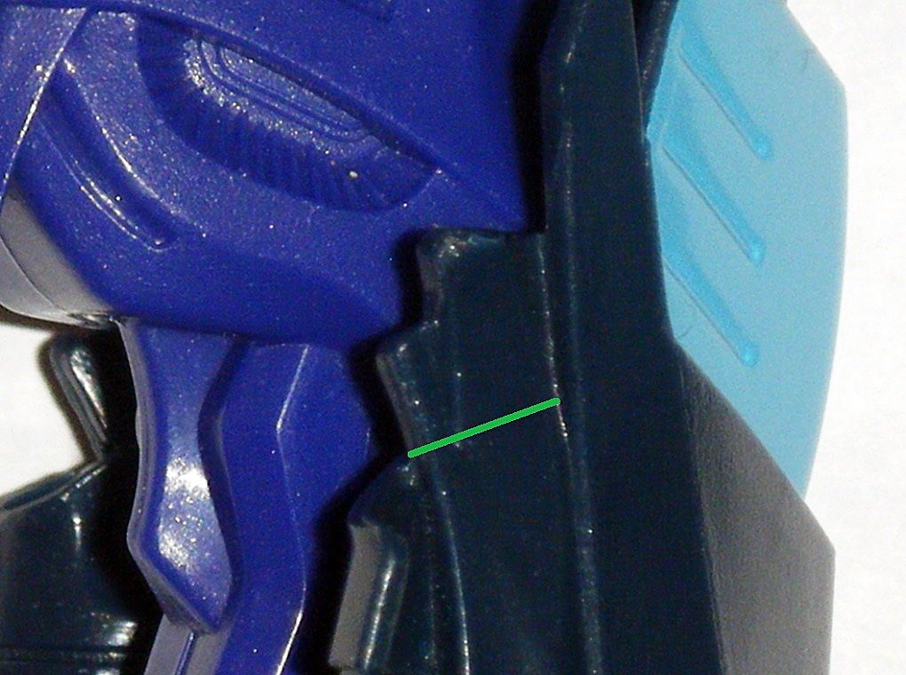
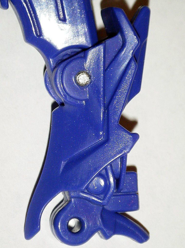
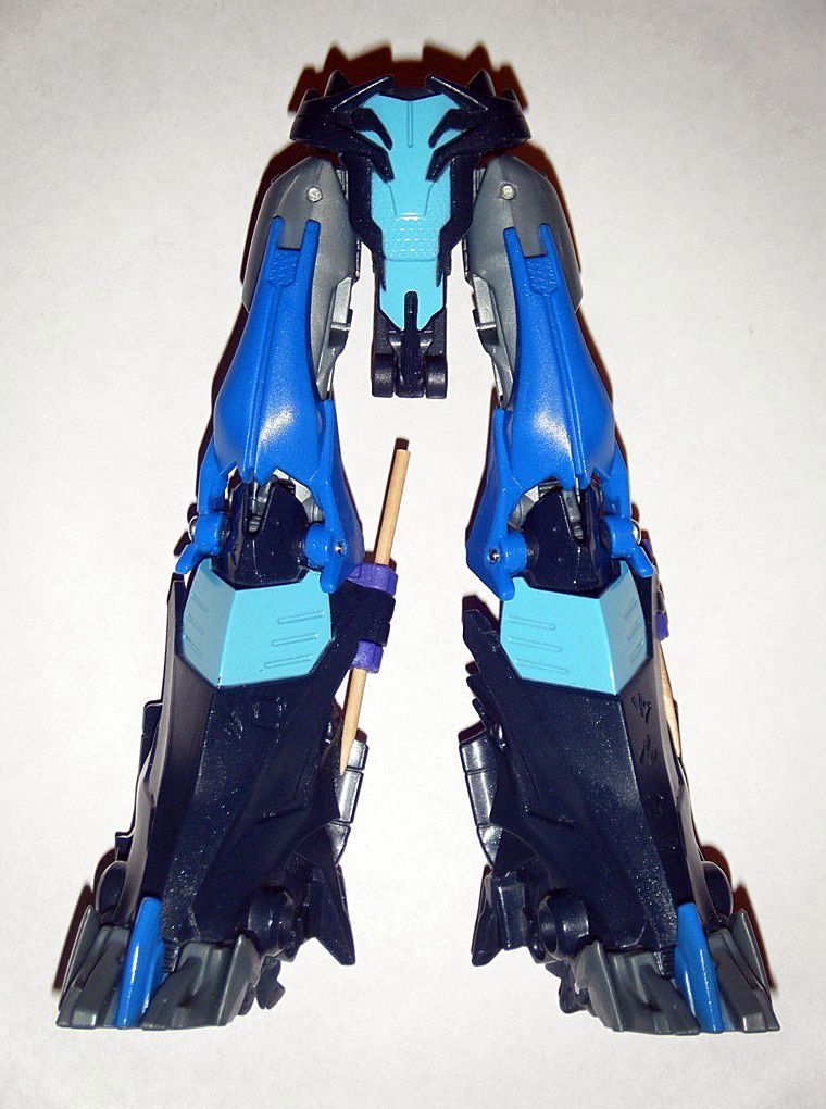
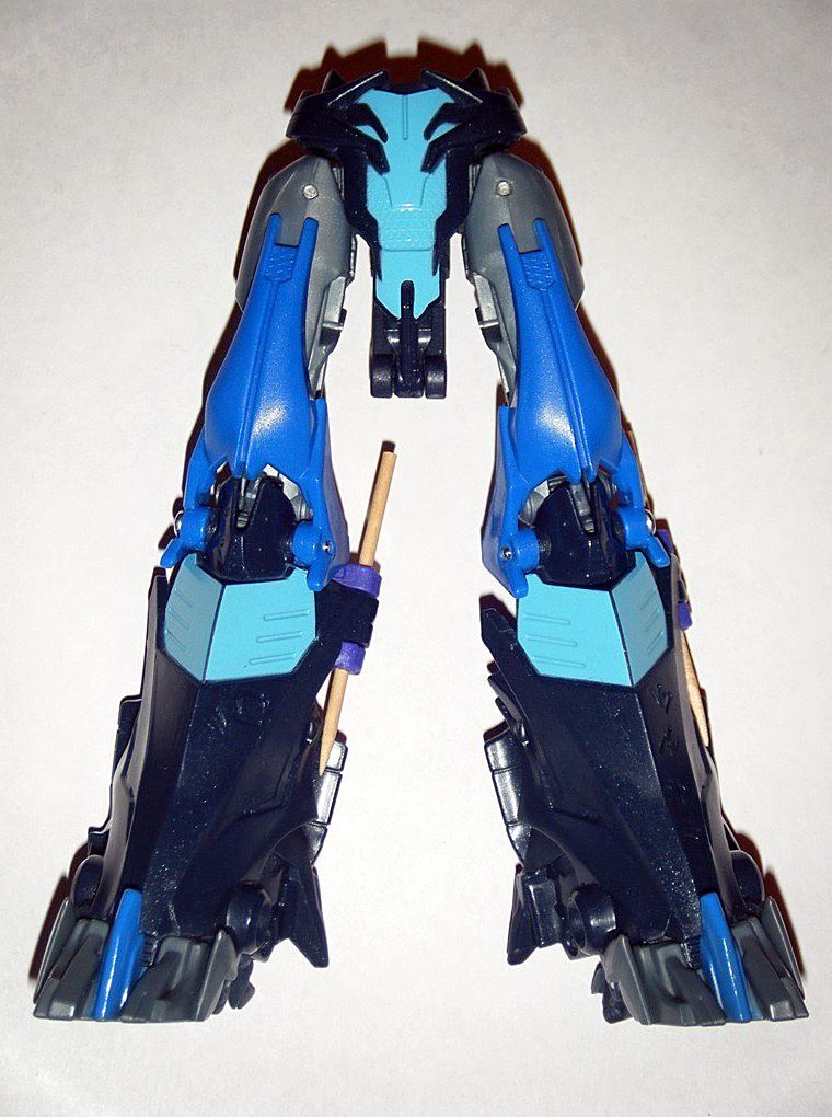
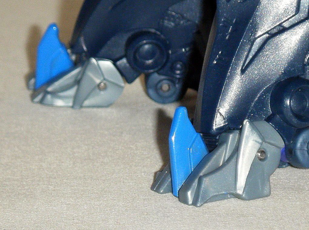
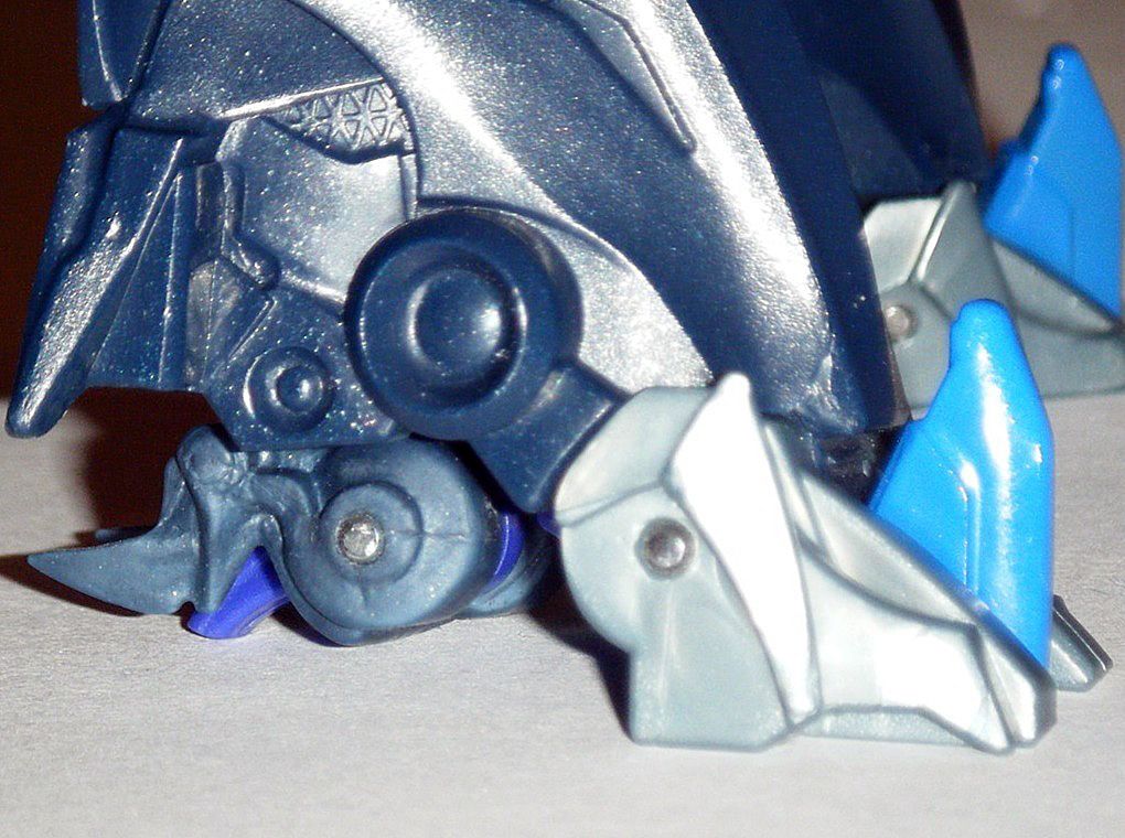
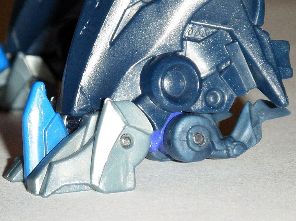
 H) ROBOT MODE HIP & LEGS:
01) Used
Gorilla Clear Glue to glue the spring lock piece on to prevent it from falling off and losing it:
02) Used
X-ACTO #11 Classic Fine Point Knife to scrape off the light blue paint on the front lower area of the hip:
03) Carefully disassembled the legs by first cutting off the plastic area (above the
green line) below the rivet joint that held the alternate mode legs in place in order to hammer out rivets and set alternate mode legs side:
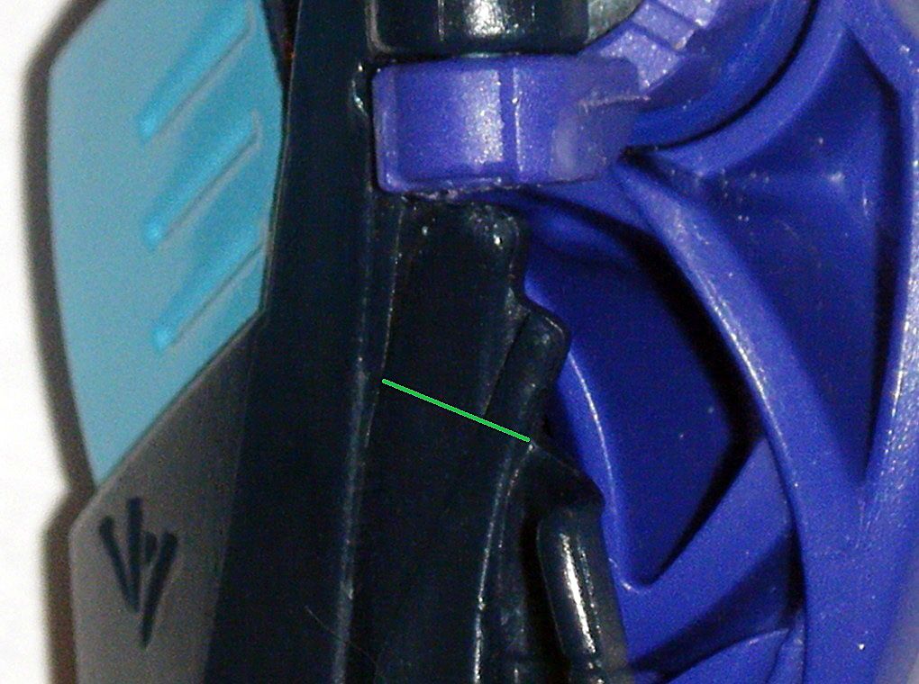
04) Same plastic area (above the
green line) on the opposite side was cut off as well to maintain symmetry:
05) Hammered out long rivet holding robot mode thigh and knee pad to lower leg in order to completely disassemble whole leg:
06) Hip joints on thighs where removed,
Gorilla Clear Glue was spread on the rivet holes, then hardened up quick by inserting a rivet and twisting it to give them tighter movement:
07)
Gorilla Clear Glue was spread on the rivet holes of knee joints, then hardened up quick by inserting a rivet and twisting it to give them tighter movement:
08)
Gorilla Clear Glue was spread in the upper disk joint and left to cure for a week in order to give them tighter movement:
09) The rivet holes on the knee of lower leg and blue knee pad were carefully widened to fit the new shortened
Philips head long screws from 2 junk
ROTF Leader Megatrons:
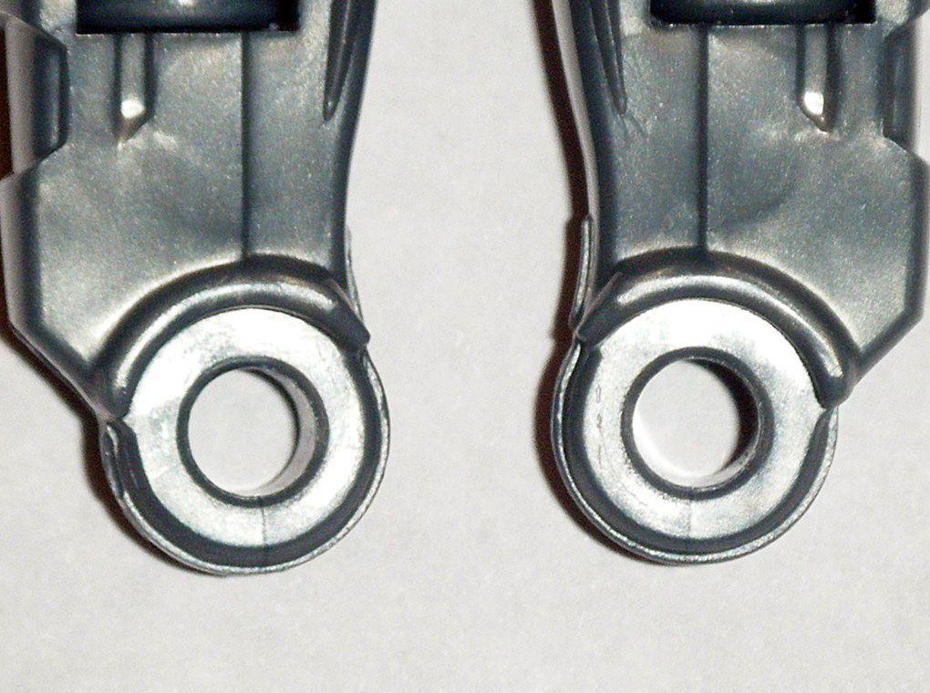
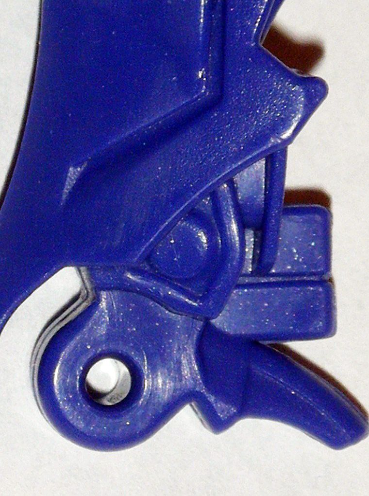
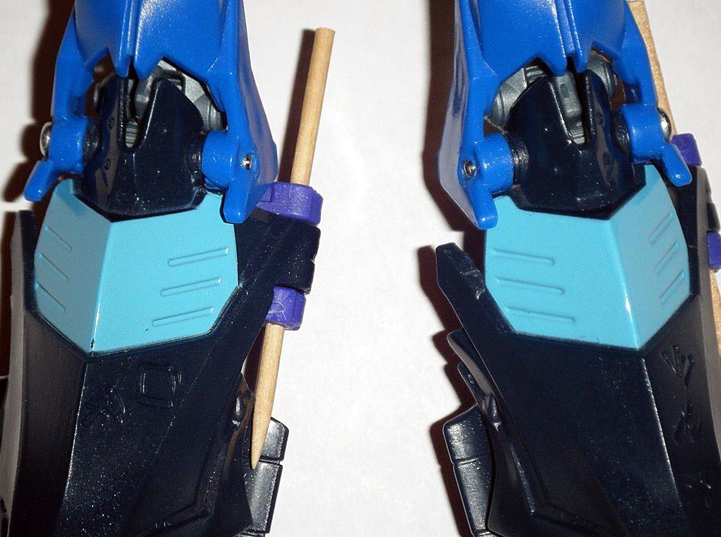
10) Area in back of foot joint was reshaped and polished to further accommodate the alternate mode legs:
11) Hole on foot joint was slightly widened with an
ACE 5/64” drill bit at low speed so the new metal rivet that will hold the robot mode foot will fit and top of right side of rivet hole was reshaped with
Dremel 463 Rubber Polishing Tapered Point to allow the rivet to slide in:
13) Used spike to carefully apply small aligned holes on left and right side of robot mode foot in order to carefully drill hole through at low speed for new rivet using, in order
Dremel 1/32”,
3/64”,
1/16” drill bits,
ACE 5/64” drill bit:
14) Used long rivets to reattach foot to lower leg, cut off rough end of river and shortened it further until rivet was completely concealed:
RESULT: Thigh, knee, and foot joints move tightly.
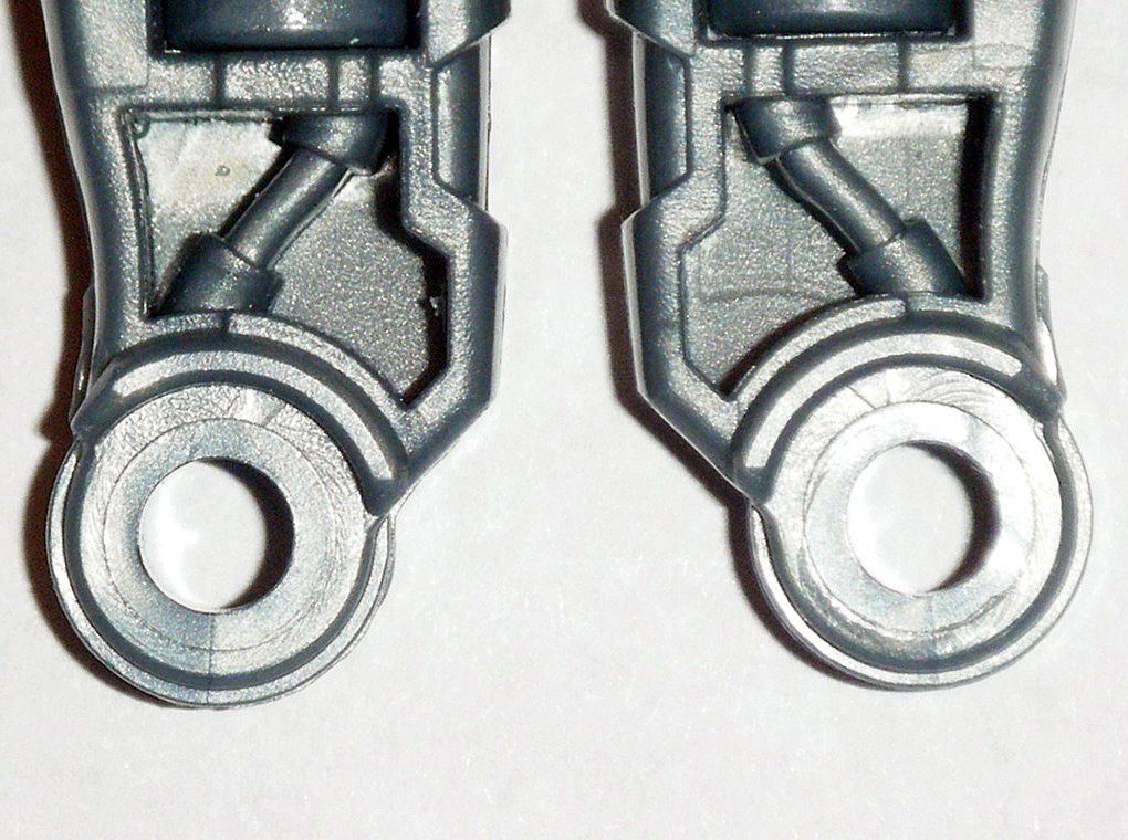
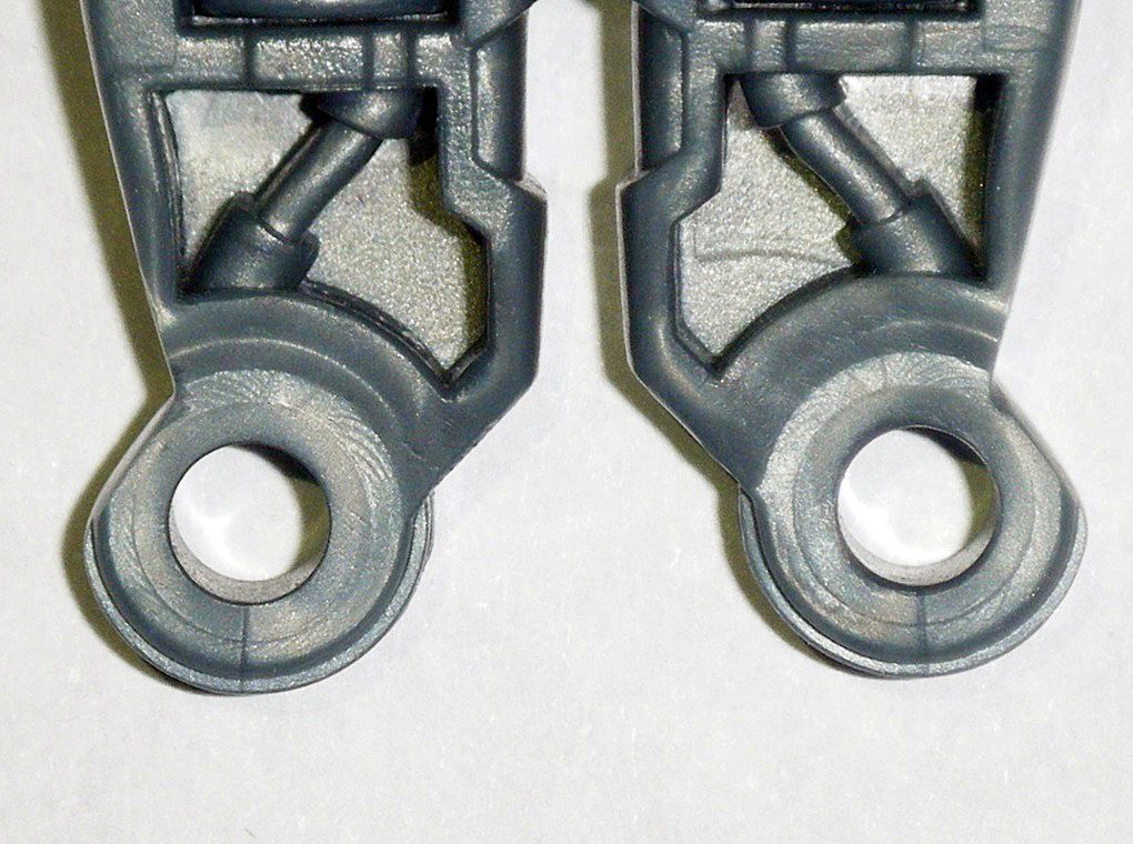
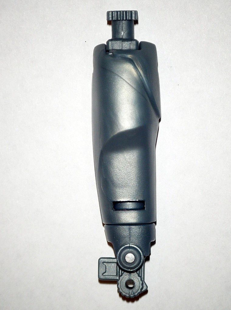
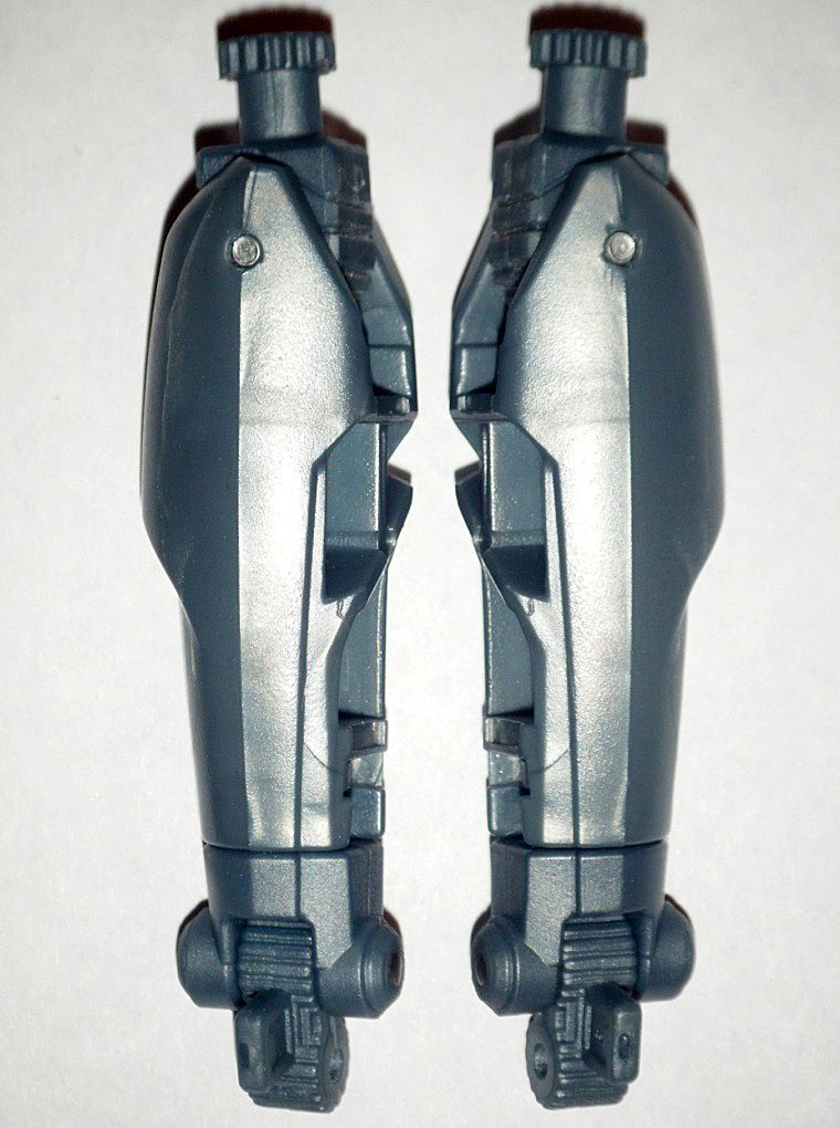
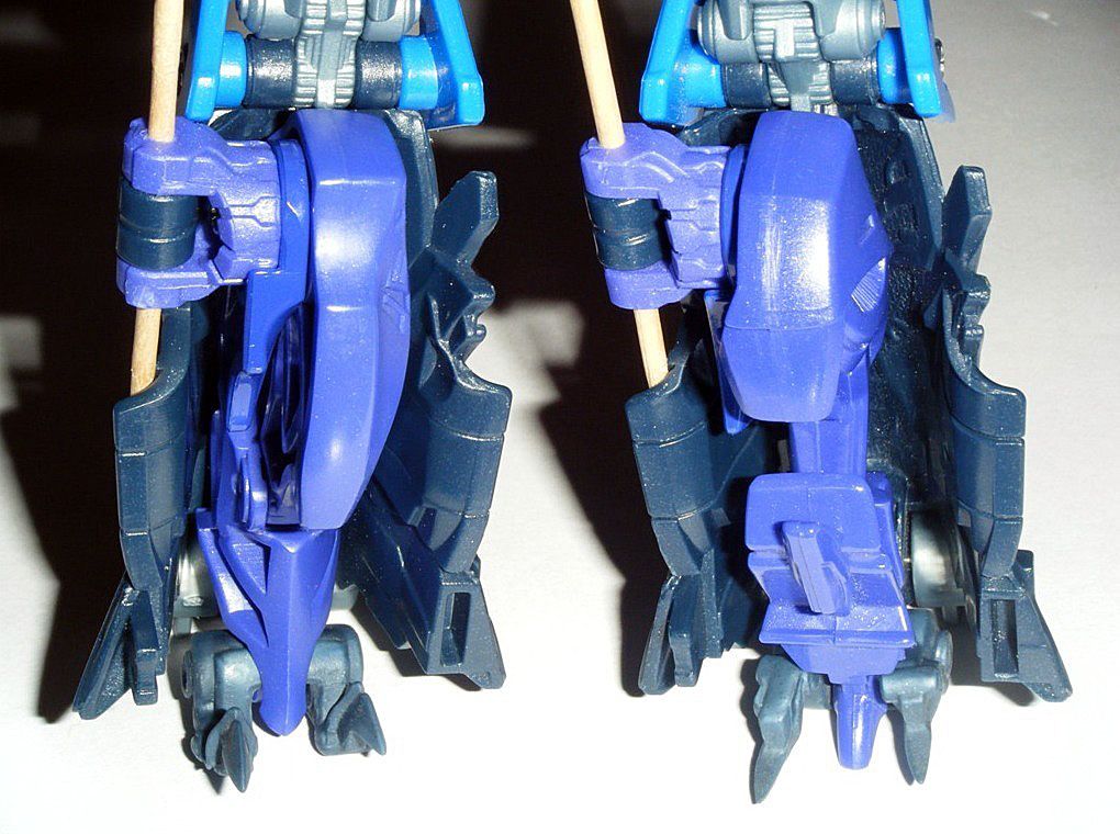
 I) ALTERNATE MODE LEGS:
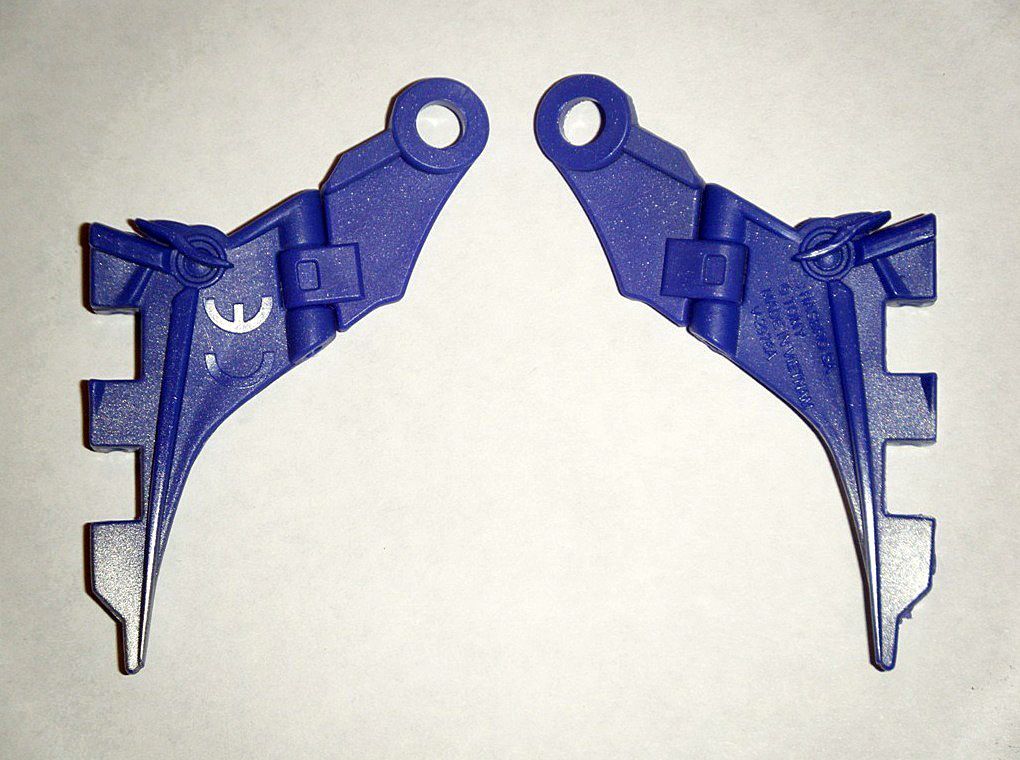
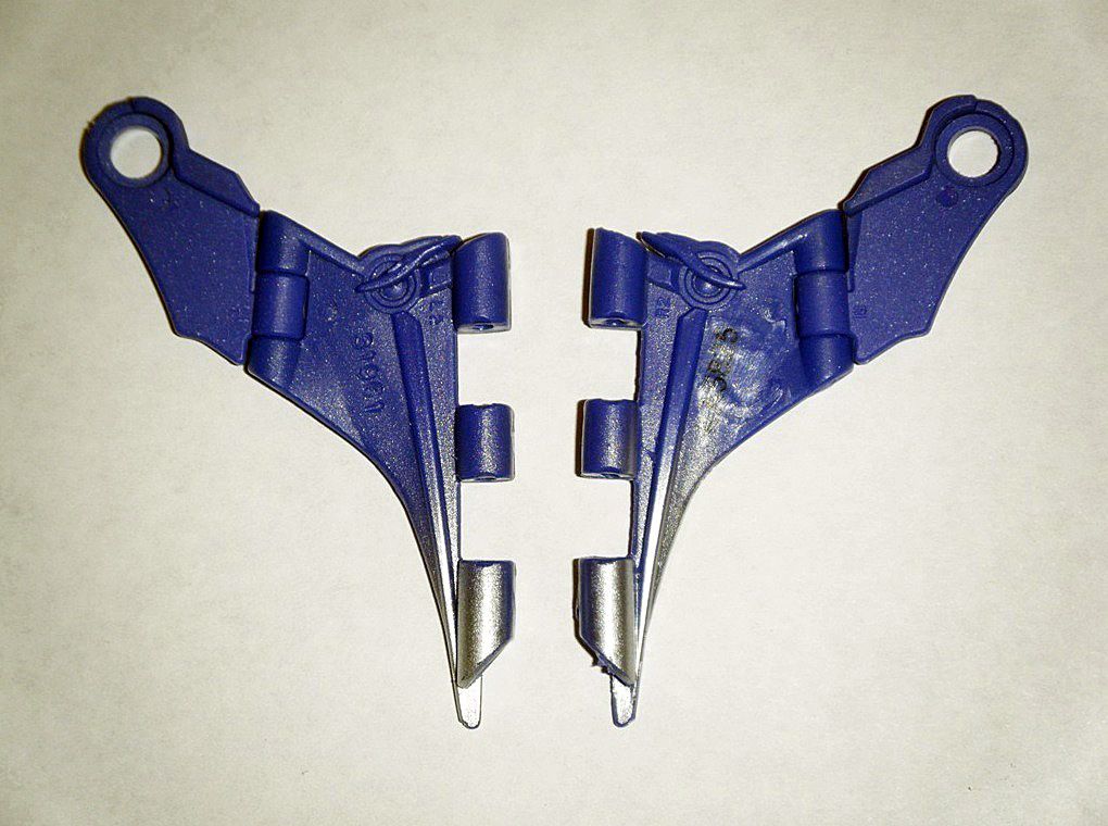
These were by far the most difficult parts I modified:
01) Removed Philips washer head screw, purple joint, and curved plate from leg:
02) Carefully sanded and polished off inside of curved hip plate so the purple hip joint can move without the curved plate moving with it:
03) Bottom edges of hip joint were carefully sanded and polished down to further prevent the curved hip plate from moving with the hip joint:
04) To allow the curved hip place to fold in the alternate mode thigh and not stick out when in robot mode yet fold back out when in alternate mode, the following was done:
Used
X-ACTO #11 Classic Fine Point Knife to carve line so that the plastic area on the right side of it will remain intact:
Carefully sanded and polished down the inner plastic on the left side of carved line:
Carefully sanded and polished down the inner plastic on the right side of carved line that remained intact:
Reinstalled curved hip plate, hip joint, and Philips washer head screw:
Now, the curved hip plates can remain in original place in alternate mode yet fold down into of the alternate mode thighs in robot mode:
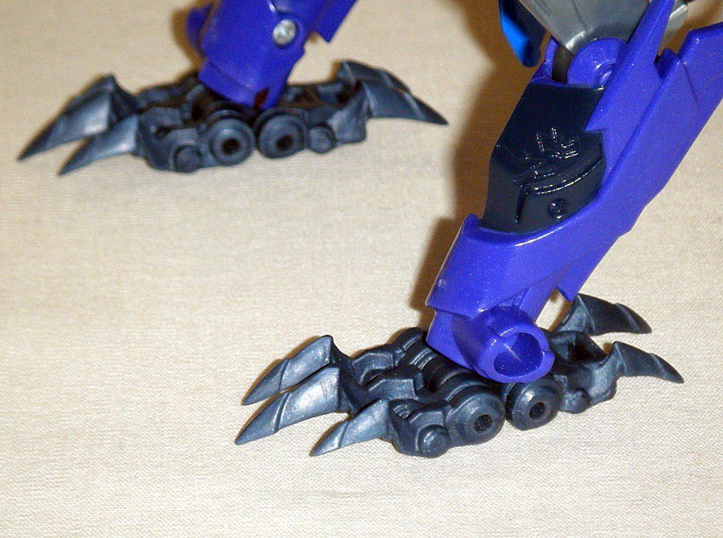
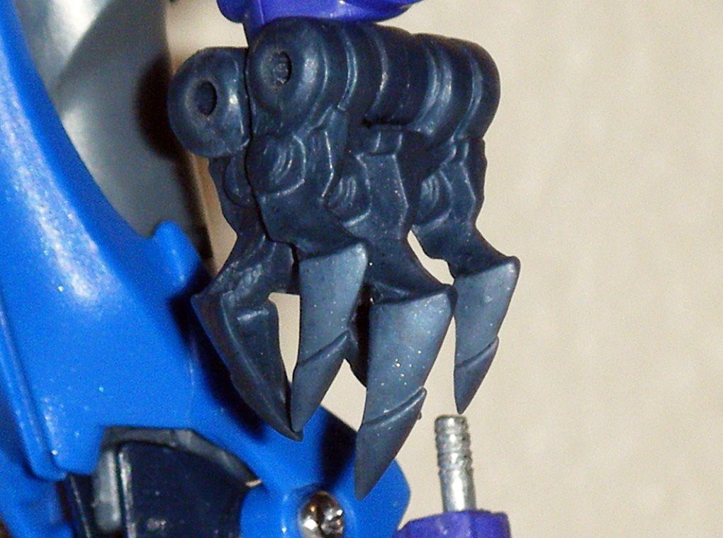
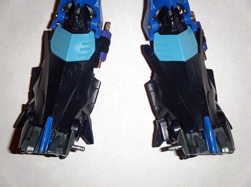
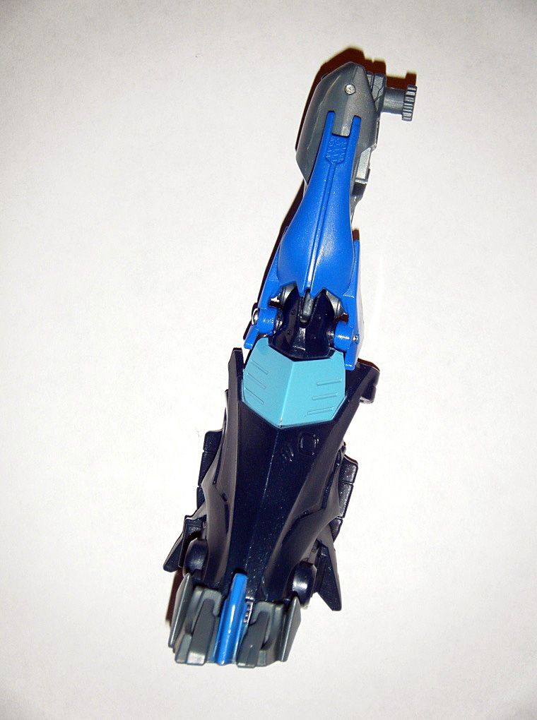
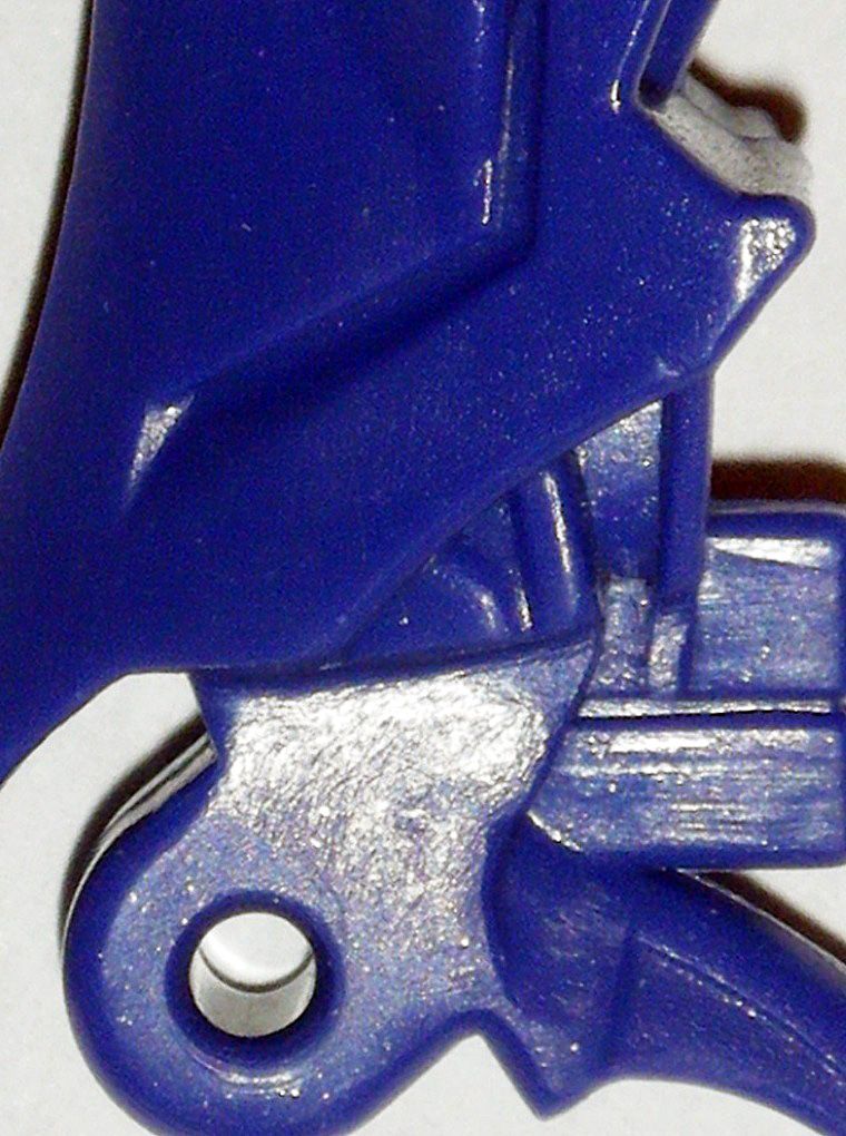
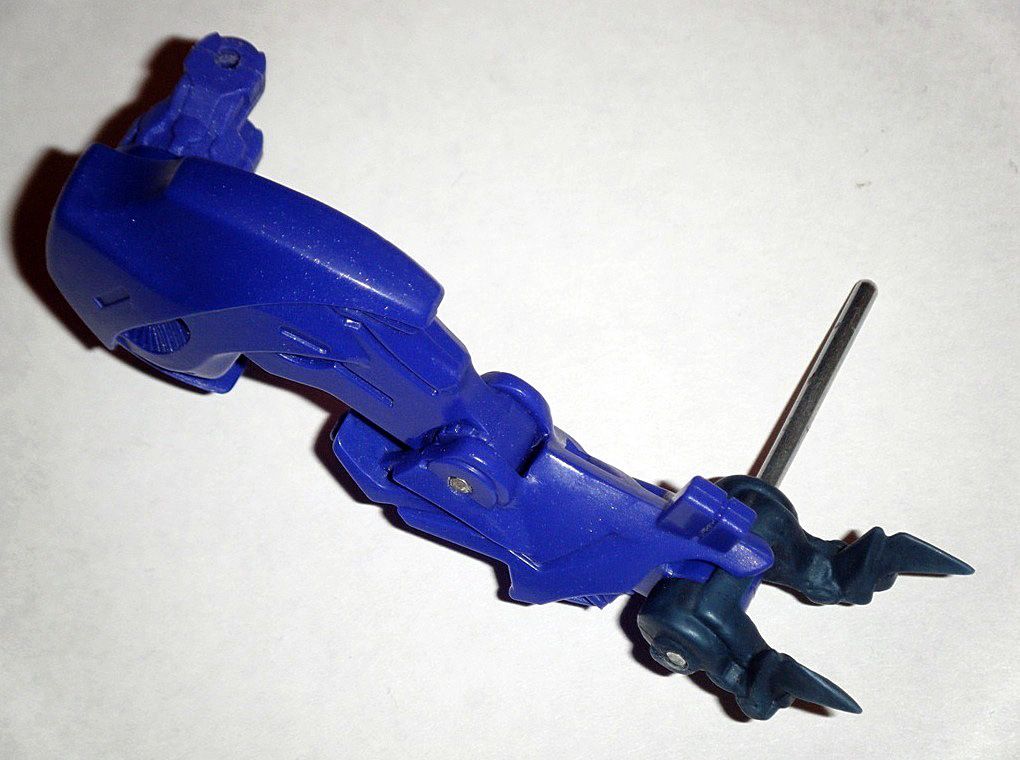
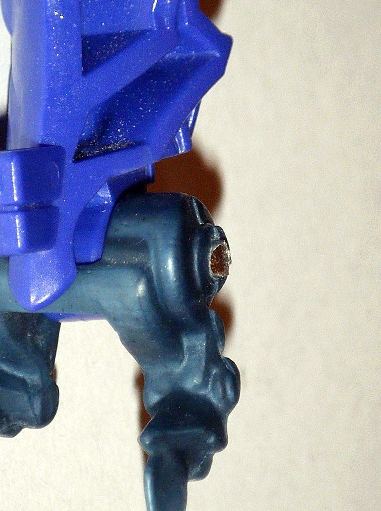
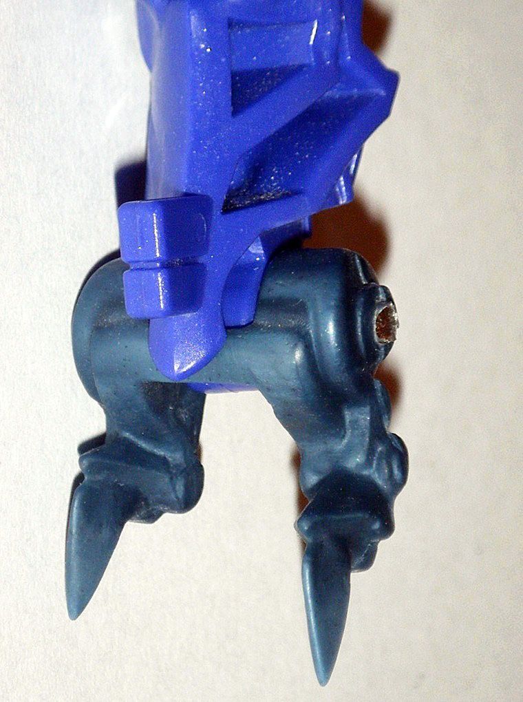
05) Removed alternate mode rubber foot/claws from lower leg:
06) Removed long spikes near rivet joint and carefully sanded/polished area:
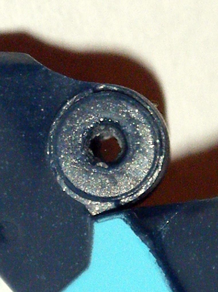
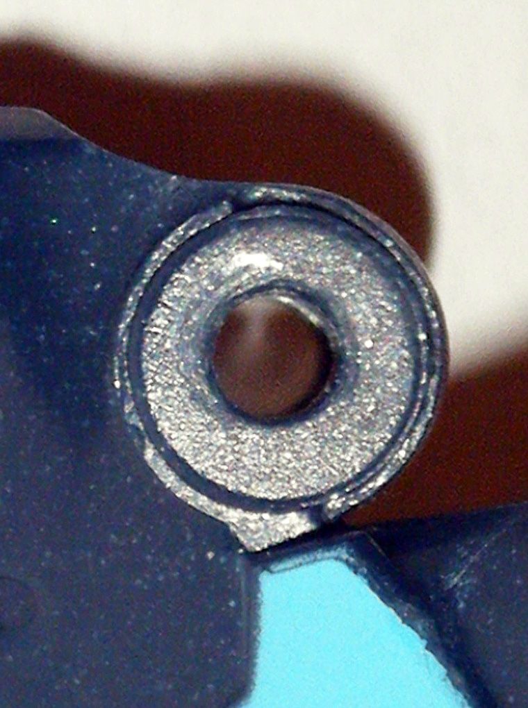
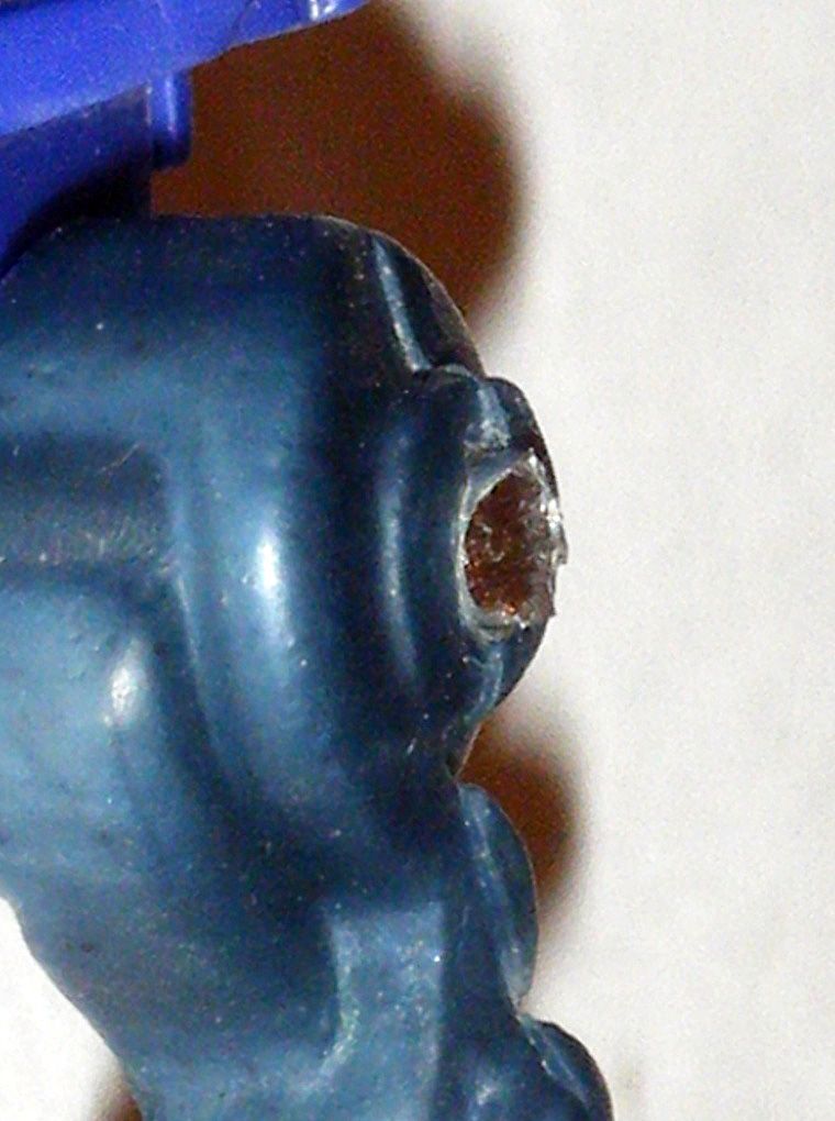
07) Used an
ACE 5/64” drill bit at low speed to drill in new rivet hole:
08) After drilling, joint became immovable. Carefully sanding/polishing rivet hole area was required to make to movable again:
09) Cut and shortened long rivets from wings of a junk
[B]2007 Movie Leader Megatron[/B] until they completely fit inside new rivet hole:
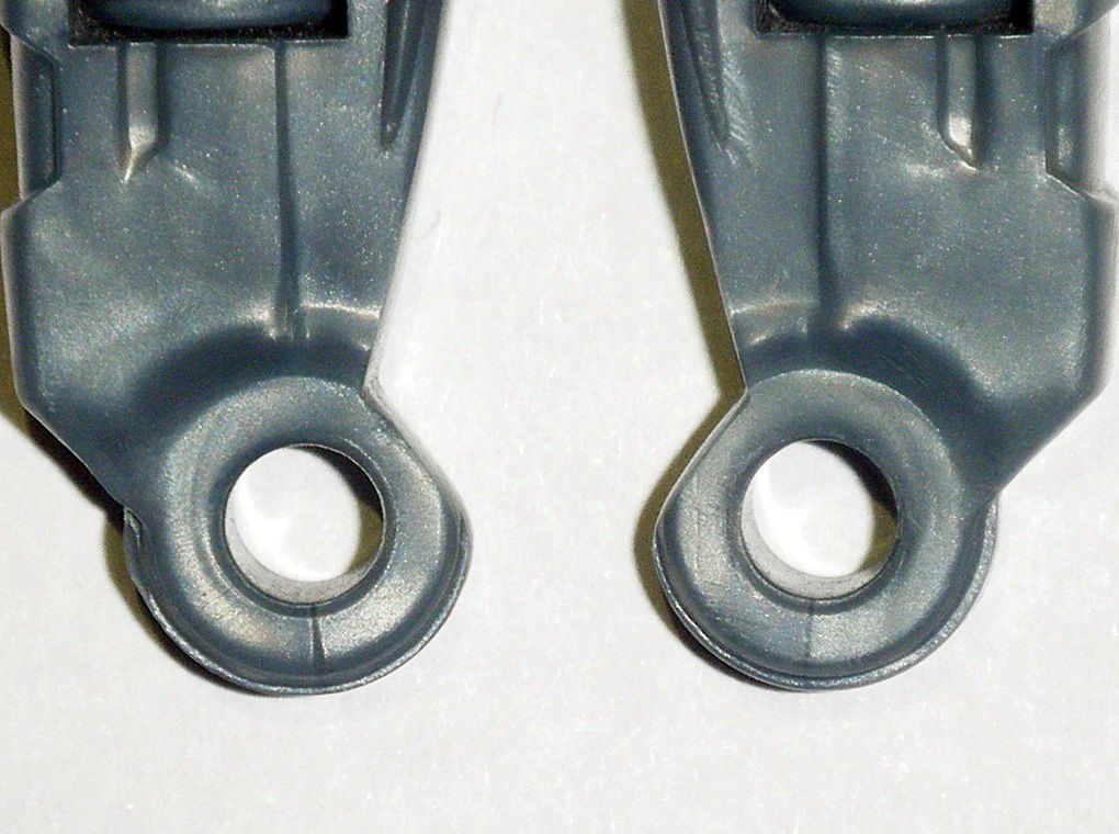
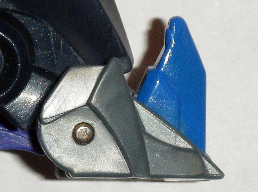
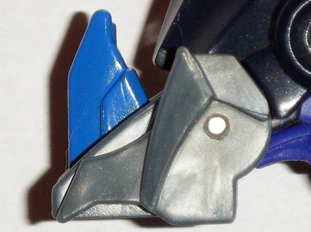
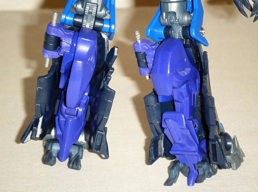
10) In order to set the robot mode foot flat on the ground therefore giving the robot mode greater stability, the following was done:
Right and left plastic areas near rubber foot/claw were carefully sanded and polished. Rivet hole on outer sides were reshaped with
Dremel 463 Rubber Polishing Tapered Point to allow the rivet to slide in:
Claws were carefully sanded down to points and the long inner area shortened:
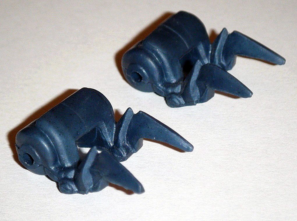
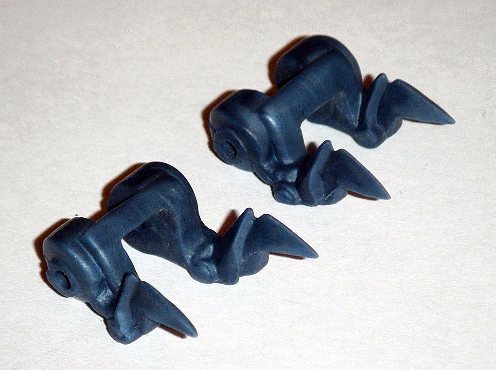
Long rivet was inserted through right side of modified rubber foot/claws:
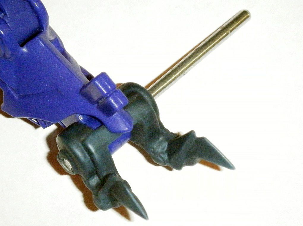
Used cutting pliers to cut off rivet at edge of modified rubber foot/claws:
Shortened rivet until left side was on level with right hole of modified rubber foot/claws and until right side of rivet when slightly under right hole of modified rubber foot/claws:
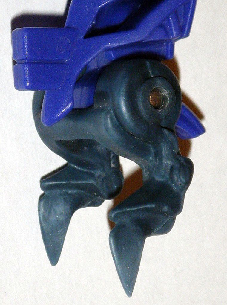
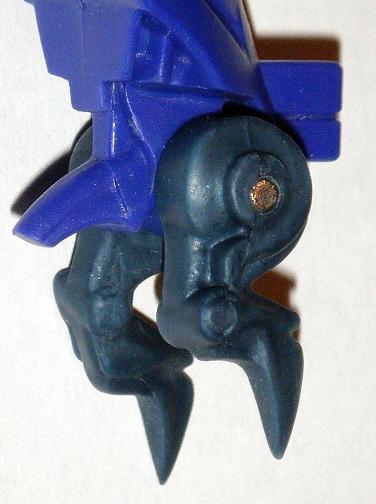
11) Alternate mode hind legs are complete:
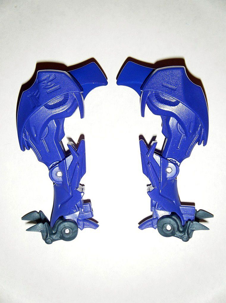
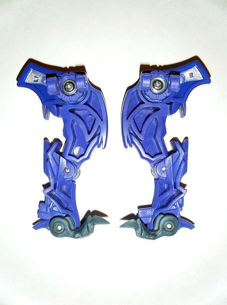
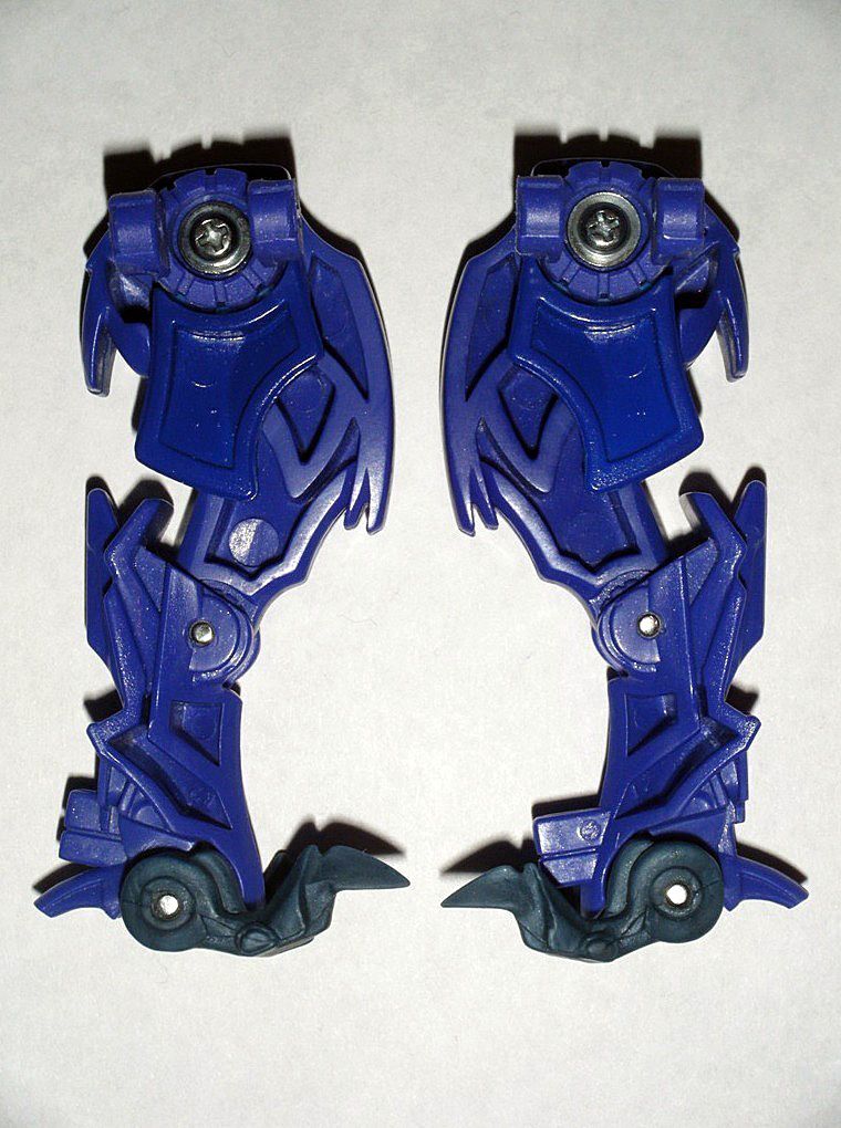
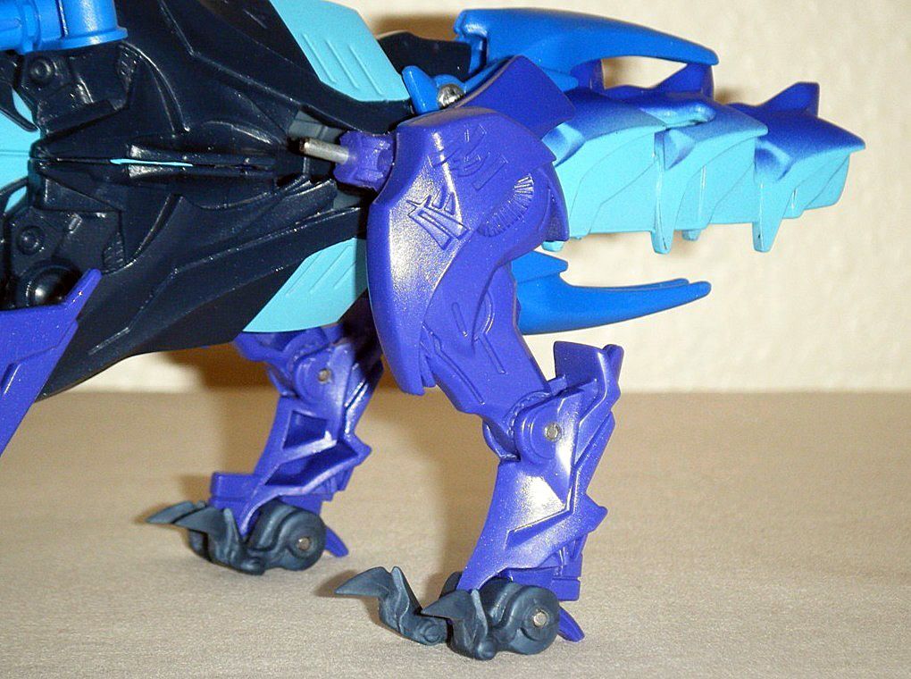
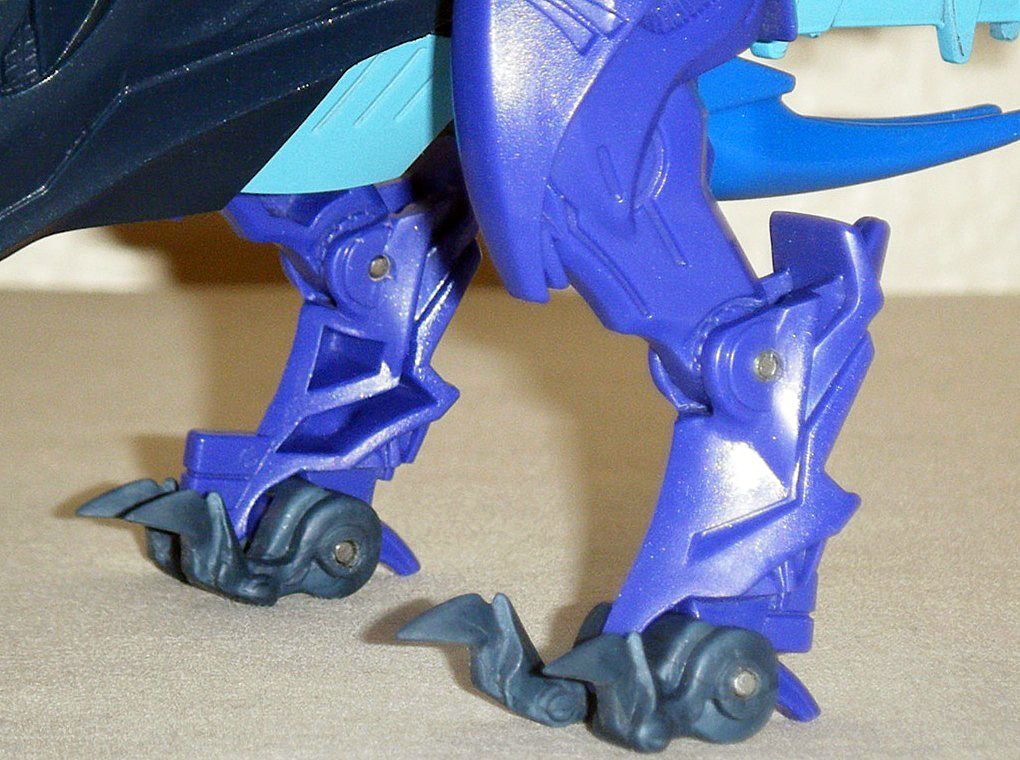
12) To allow the modified alternate mode hind legs to fit perfectly inside the robot mode legs, the plastic on the inner left side was carefully sanded/polished down:
13) Robot mode hip and legs reassembled:
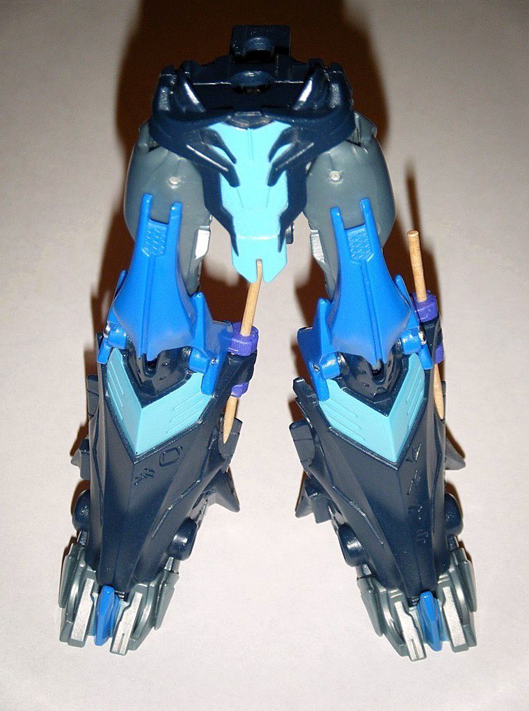
14) As a finishing touch, an
X-ACTO #10 General Purpose Blade was used to carefully scrape off the light blue paint at the middle edge of the area near the knee:
15) RESULT: Robot mode foot is leveled flat to the ground. Therefore
Dreadnought can stand in robot mode without the risk of tipping over. As for the alternate mode hind legs, joints are tight and it functions better than before.
PHASE 2, will probably be more challenging than PHASE 1:
Creating an alternate mode dragon tail that ends in a paddle-shaped fluke that doubles as Dreadnought’s large hand-held dagger in robot mode.In this phase, I intend to modify a
TFP Voyager Beast King Tail/Sword Complete - White Strong & Flexible from
Shapeways as the main tail body:
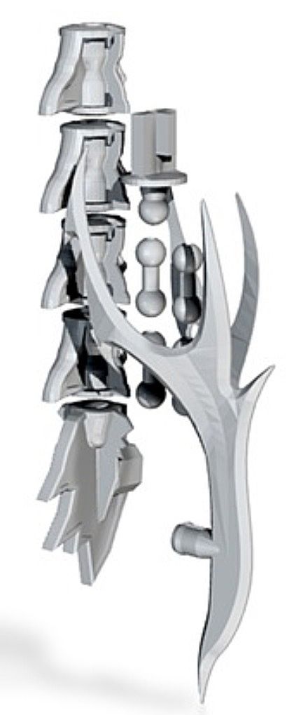
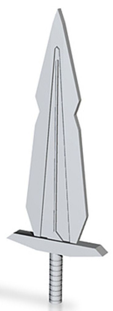
The sword that’s part of the
Sunlink - Stronghold Upgrade Kit v3 – TFCon - White Strong & Flexible from
Shapeways will be modified as the tail’s paddle-shaped fluke that doubles as
Dreadnought’s large hand-held dagger in robot mode: